Communicating with the PLC
7.2 MODBUS communication
SINAMICS V20 Converter
Operating Instructions, 10/2019, A5E34559884-012
179
P2013[0] USS PKW (parameter ID value) length Defines the number of 16-bit words in PKW part of USS telegram.
Possible settings:
= 0, 3, 4: 0, 3 or 4 words
= 127: variable length (factory default)
USS/MODBUS telegram off time [ms]
If time set to 0, no fault is generated (i.e. watchdog disabled).
r2024[0]
...
USS/MODBUS error statistics The state of the telegram information on RS485 is reported re-
gardless of the protocol set in P2023.
CO: PZD from USS/MODBUS on RS485
Displays process data received via USS/MODBUS on RS485.
CI: PZD to USS/MODBUS on RS485
Displays process data transmitted via USS/MODBUS on RS485.
P2034 MODBUS parity on RS485 Sets the parity of MODBUS telegrams on RS485.
Possible settings:
= 0: no parity
= 1: odd parity
P2035 MODBUS stop bits on RS485 Sets the number of stop bits in MODBUS telegrams on RS485.
Possible settings:
= 1: 1 stop bit
7.2 MODBUS communication
Overview
In MODBUS, only the master can start a communication and the slave will answer it. There
are two ways of sending a message to a slave. One is unicast mode (address 1 to 247),
where the master addresses the slave directly; the other is broadcast mode (address 0),
where the master addresses all slaves.
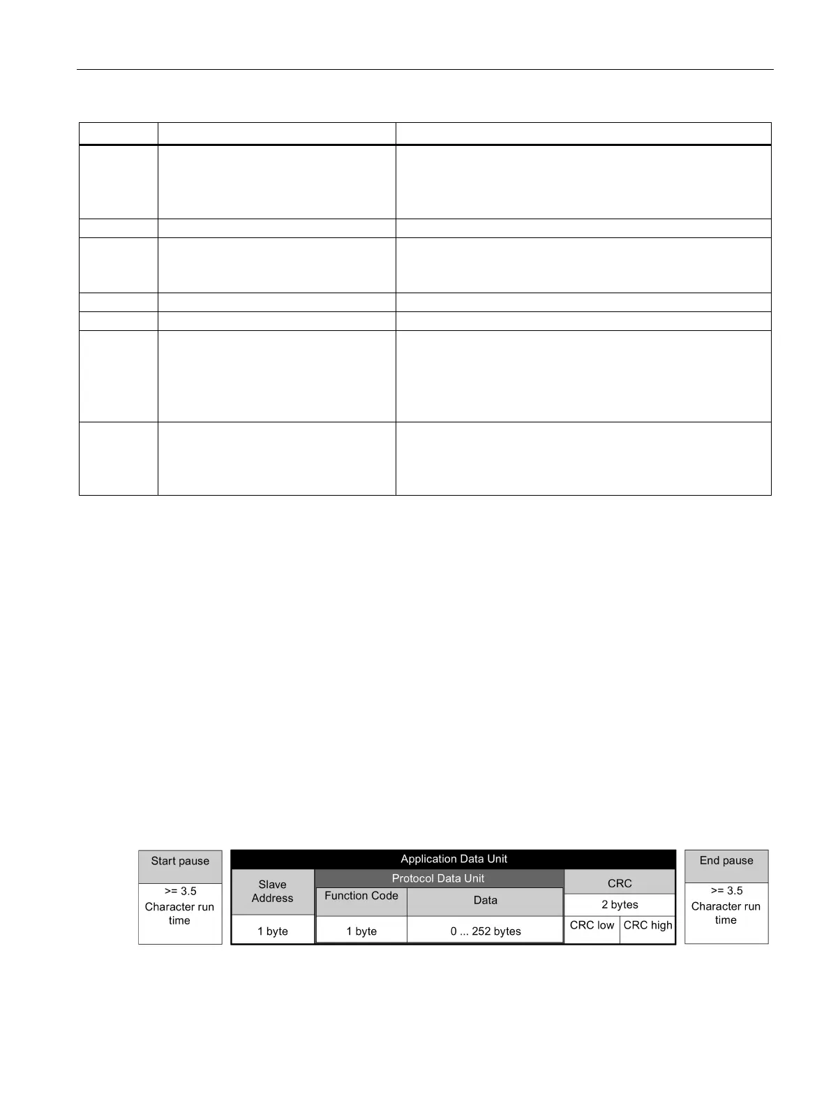
When a slave has received a message, which was addressed at it, the Function Code tells it
what to do. For the task defined by the Function Code, the slave may receive some data.
And for error checking a CRC code is also included.
After receiving and processing a unicast message, the MODBUS slave will send a reply, but
only if no error was detected in the received message. If a processing error occurs, the slave
will reply with an error message. The following fixed framing characters in a message cannot
be altered: 8 data bits, 1 parity bit, and 1 or 2 stop bits.