2 Functions
132
7SD5 Manual
C53000-G1176-C169-1
The characteristic for the load angle range has to be set in a way that is just below the
minimum expected operating voltage at the maximum expected load current. In the
range of the short-circuit angles ϕ
K
it must be ensured that load current may not cause
pickup in this area. If reactive power has to be transferred via this line, it must be
ensured that the maximum reactive current at minimum operating voltage is not within
the pickup range, i.e. the short-circuit angle range ϕ
K
. If in doubt, check the pickup con-
ditions in accordance with the U/I/ϕ characteristic. An arithmetic short-circuit calcula-
tion is recommended for extensive networks.
The lower threshold angle ϕ> (address 1920) should be between the load angle and
the short-circuit angle. Therefore it must be set smaller than the line angle ϕ
L
= arctan
(X
L
/R
L
) (approx. 10° to 20°). Subsequently, you should check that the angle is not ex-
ceeded during load conditions. If this is the case, for instance because the reactive
power has to be transferred via this line, it must be ensured that the parameters of the
voltage-dependent segment d, that is Iphi> and Uph-e (Iphi>) or Uph-ph
(Iphi>) rule out a pickup as the result of reactive power (see above).
The upper threshold angle ϕ< (address 1921) is not critical. 100° to 120° should be
sufficient in all cases.
Angular dependence, i.e. increasing the sensitivity for a large short-circuit angle with
section d and e in the characteristic, can be limited to the forward direction (line direc-
tion) using address 1919 EFFECT ϕ. In this case, EFFECT ϕ is set to Forward. Oth-
erwise EFFECT ϕ = forward&reverse. This setting is only possible via DIGSI
®
at
"Additional Settings".
2.5.1.5 Settings
Addresses which have an appended "A" can only be changed with DIGSI, under Ad-
ditional Settings.
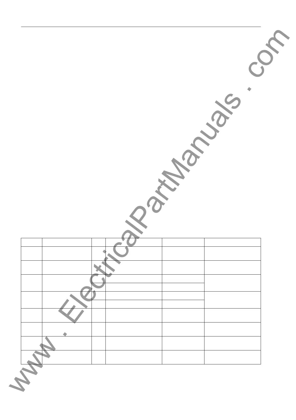
The table indicates region-specific presettings. Column C (configuration) indicates the
corresponding secondary nominal current of the current transformer.
Addr. Parameter C Setting Options Default Setting Comments
1218 T3I0 1PHAS 0.00 .. 0.50 sec; ∞ 0.04 sec Delay 1ph-faults
(comp/isol. star-point)
1501 FCT Distance ON
OFF
ON Distance protection
1502 Minimum Iph> 1A 0.05 .. 4.00 A 0.10 A Phase Current threshold
for dist. meas.
5A 0.25 .. 20.00 A 0.50 A
1503 3I0> Threshold 1A 0.05 .. 4.00 A 0.10 A 3I0 threshold for neutral
current pickup
5A 0.25 .. 20.00 A 0.50 A
1504 3U0> Threshold 1 .. 100 V; ∞ 5 V 3U0 threshold zero seq.
voltage pickup
1505 3U0> COMP/ISOL. 10 .. 200 V 40 V 3U0> pickup (comp/ isol.
star-point)
1507A 3I0>/ Iphmax 0.05 .. 0.30 0.10 3I0>-pickup-stabilisation
(3I0> /Iphmax)
1508 SER-COMP. NO
YES
NO Series compensated line
www . ElectricalPartManuals . com
 Loading...


