2.24 Ancillary Functions
421
7SD5 Manual
C53000-G1176-C169-1
2.24.3 Statistics
2.24.3.1 Functional Description
Switching Statistics The messages in switching statistics are counters for the accumulation of interrupted
currents by each of the breaker poles, the number of control commands issued by the
device 7SD5 to the breakers, and the maximum interrupted currents. The indicated
measured values are indicated in primary values.
Switching statistics can be viewed on the LCD of the device, or on a PC running
DIGSI
®
and connected to the operator or service interface.
The counters and memories of the statistics are saved by the device. Therefore the
information will not get lost in case the auxiliary voltage supply fails. The counters,
however, can be reset back to zero or to any value within the setting range.
A password is not required to read counter and stored values but is required to change
or delete them. For further information see the SIPROTEC
®
4 System Description.
Transmission
Statistics
In 7SD5 the protection communication is registered in statistics. The transmission
times of the information between the devices via interfaces (send and receive) are
measured continuously. The values are kept stored in the statistics folder. The avail-
ability of the transmission media is also reported. The availability is indicated in % min
and % h. This enables an evaluation of the transmission quality.
If GPS synchronization is configured, the transmission times for each direction and
each protection data interface are regularly measured and indicated as long as GPS
synchronization is intact.
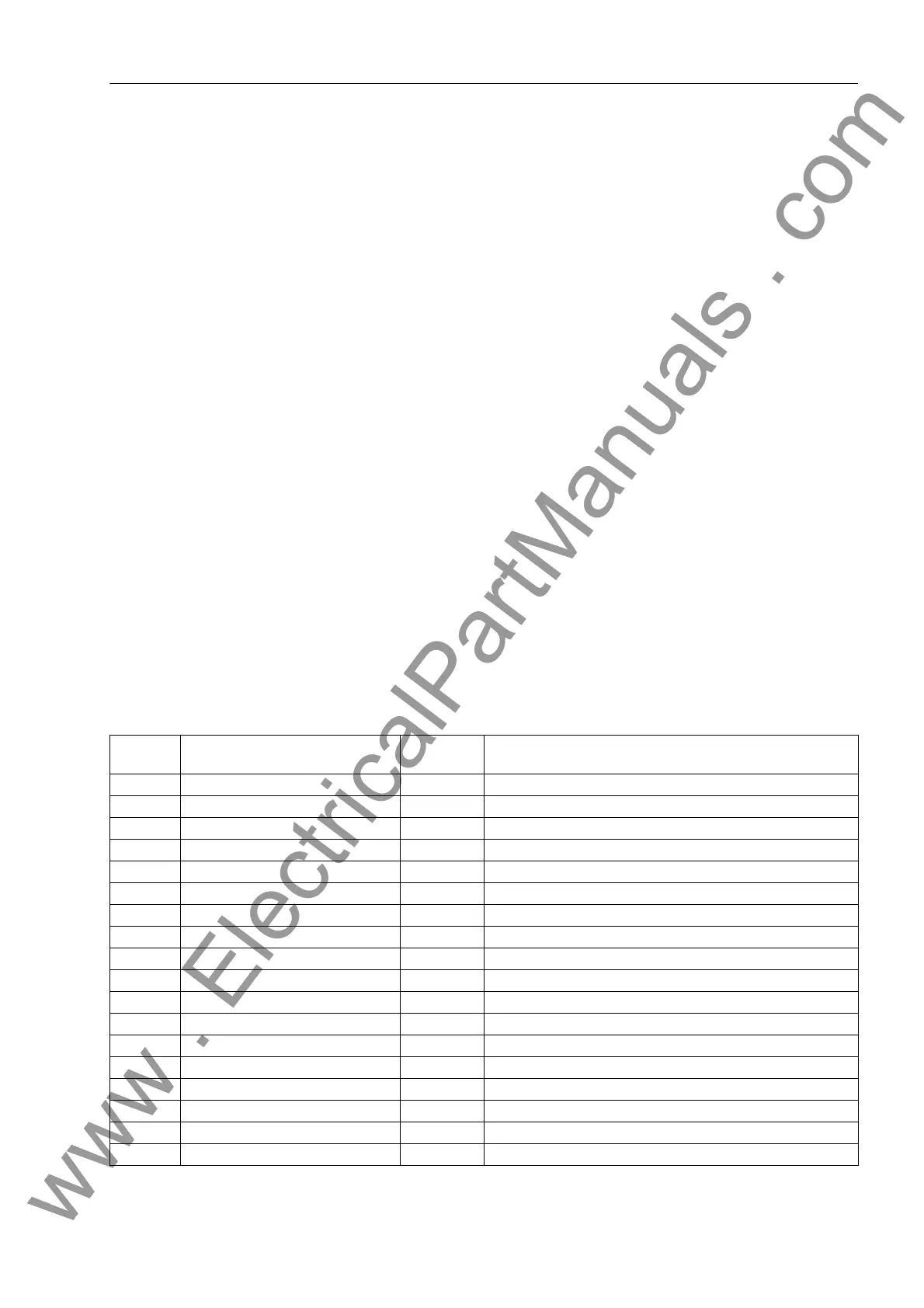
2.24.3.2 Information List
No. Information Type of In-
formation
Comments
1000 # TRIPs= VI Number of breaker TRIP commands
1001 TripNo L1= VI Number of breaker TRIP commands L1
1002 TripNo L2= VI Number of breaker TRIP commands L2
1003 TripNo L3= VI Number of breaker TRIP commands L3
1027 Σ IL1 = VI Accumulation of interrupted current L1
1028 Σ IL2 = VI Accumulation of interrupted current L2
1029 Σ IL3 = VI Accumulation of interrupted current L3
1030 Max IL1 = VI Max. fault current Phase L1
1031 Max IL2 = VI Max. fault current Phase L2
1032 Max IL3 = VI Max. fault current Phase L3
2895 AR #Close1./1p= VI No. of 1st AR-cycle CLOSE commands,1pole
2896 AR #Close1./3p= VI No. of 1st AR-cycle CLOSE commands,3pole
2897 AR #Close2./1p= VI No. of higher AR-cycle CLOSE commands,1p
2898 AR #Close2./3p= VI No. of higher AR-cycle CLOSE commands,3p
7751 PI1 TD MV Prot.Interface 1:Transmission delay
7752 PI2 TD MV Prot.Interface 2:Transmission delay
7753 PI1A/m MV Prot.Interface 1: Availability per min.
7754 PI1A/h MV Prot.Interface 1: Availability per hour
www . ElectricalPartManuals . com
 Loading...


