4 Technical Data
526
7SD5 Manual
C53000-G1176-C169-1
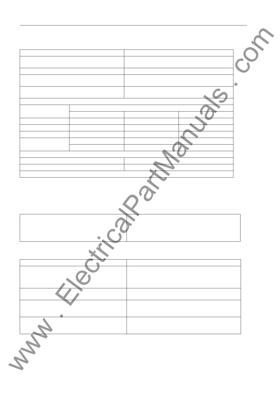
Time Synchronization Interface
4.1.5 Electrical Tests
Specifications
Insulation Test
Time synchronization DCF 77/IRIG-B-Signal (telegram format IRIG-B000)/GPS
Connection for panel flush mounting housing Rear panel, slot „A“
9-pole D-subminiature female connector
For panel surface mounting housing At two-tier terminals on housing bottom
Nominal signal voltages
DCF77/IRIG B
Selectable 5 V, 12 V or 24 V
Nominal signal voltages
GPS
24 V
Signal levels and burdens DCF77/IRIG-B:
Nominal signal input voltage
5V 12V 24V
U
IIHigh
6.0 V 15.8 V 31 V
U
ILow
1.0 V at I
ILow
= 0.25 mA 1.4 V at I
ILow
= 0.25 mA 1.9 V at I
ILow
= 0.25 mA
I
IHigh
4.5 mA to 9.4 mA 4.5 mA to 9.3 mA 4.5 mA to 8.7 mA
R
I
890 Ω at U
I
= 4 V 1930 Ω at U
I
= 8.7 V 3780 Ω at U
I
= 17 V
640 Ω at U
I
= 6 V 1700 Ω at U
I
= 15.8 V 3560 Ω at U
I
= 31 V
PPS Signal for GPS
ON/OFF pulse duty factor 1/999 to 1/1
max. rise/fall time deviation of all receivers ±3 µs
For GPS receiver, antenna and power supply unit please refer to Appendix A1.2, Accessories.
Standards: IEC 60255 (product standards)
IEEE Std C37.90.0/.1/.2
UL 508
VDE 0435
For more standards see also individual functions
Standards: IEC 60255-5 and IEC 60870-2-1
High voltage test (routine test)
All circuits except power supply, Binary Inputs, High
Speed Outputs, Communication Interface and Time Syn-
chronization Interfaces
2.5 kV (rms), 50 Hz
High voltage test (routine test)
Auxiliary voltage, binary inputs and high speed outputs
3.5 kVDC
High voltage test (routine test)
only isolated communication and time synchronisation
interfaces
500 V (rms), 50 Hz
Impulse voltage test (type test)
All Circuits Except Communication and Time Synchroni-
zation Interfaces, Class III
5 kV (peak), 1.2/50 µs, 0.5 Ws, 3 positive and 3 negative im-
pulses in intervals of 5 s
www . ElectricalPartManuals . com
 Loading...


