Do you have a question about the Siemens siprotec 7SD5 and is the answer not in the manual?
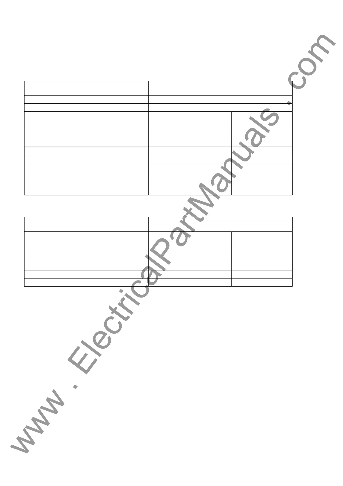
| Rated Frequency | 50/60 Hz |
|---|---|
| Current Input | 1 A / 5 A |
| Display | LCD |
| Voltage Supply | 24-250 V DC / 100-240 V AC |
| Communication Interfaces | Ethernet, RS485, USB |
| Protocols | IEC 61850, DNP3, Modbus |
| Protection Functions | Overcurrent, Distance |
| Mounting | Panel mounting |
| Operating Temperature | -25°C to +70°C |
Describes the content and structure of the manual for the 7SD5 device.
Identifies the intended readers for this manual, including engineers and technicians.
Explains the meaning of DANGER, WARNING, CAUTION, and NOTE indicators used in the manual for safety.
Defines the prerequisites and qualifications required for personnel working with the device.
Explains the use of fonts, symbols, and graphical conventions within the manual.
Describes the device's microcomputer system, analog inputs, and basic structure.
Details the device's capabilities in protecting overhead lines and cables with multi-end infeeds.
Outlines general features and specific characteristics of differential and distance protection functions.
Provides general information on device settings, system data, and interaction with protection functions.
Explains the principle of differential protection, including its application for lines and busbars.
Details the distance protection function, including fault detection, impedance calculation, and characteristics.
Describes the automatic reclosure functionality, its operation, and configuration.
Covers hardware and software monitoring, including measurement supervision and malfunction responses.
Explains device control, circuit breaker position detection, and testing procedures.
Details additional functions such as commissioning tools, message processing, and fault record storage.
Provides guidance on device installation, including prerequisites and connection examples for current and voltage transformers.
Details procedures for checking serial interfaces, protection data communication, and system interfaces.
Covers essential commissioning steps, including test modes, time synchronization, and system interface checks.
Describes final checks and settings required before the device is ready for operation.
Presents general technical specifications for current inputs, auxiliary voltage, and binary inputs/outputs.
Lists technical data for differential protection, including pickup values and tripping times.
Provides technical data for distance protection, covering earth impedance, phase preferences, and fault detection.
Details technical data for automatic reclosure, including number of reclosures, control modes, and adaptive dead times.
Provides technical data for synchronism and voltage check functions, including operating modes and voltage thresholds.
Lists technical data for undervoltage and overvoltage protection stages for phase, sequence systems.
Presents technical data for frequency protection, including stages, pickup values, and operating ranges.
Provides technical data for the fault locator function, including start modes and output options.
Details technical data for circuit breaker failure protection, including current flow monitoring and delay times.
Lists technical data for thermal overload protection, including setting ranges and tripping characteristics.
Provides technical data for monitoring functions, covering hardware, software, and measurement circuit checks.
Lists technical data for user-defined functions, including function modules and task level assignments.
Provides mechanical dimensions for panel flush, cubicle, and surface mounting.
Contains information for ordering devices and accessories, including order codes and descriptions.
Details terminal assignments for panel flush, cubicle, and surface mounting for various device types.
Provides connection examples for current transformers, voltage transformers, and pilot wires.
Lists default settings for LEDs, binary inputs, binary outputs, and function keys.
Details the functional scope of the device, including protection and ancillary functions.
Provides a comprehensive table of all configurable parameters, their setting options, and default values.
Lists all device information, including status signals, fault indications, and measurement values.


