4.2 Protection Data Interfaces and Differential Protection Topology
531
7SD5 Manual
C53000-G1176-C169-1
4.2 Protection Data Interfaces and Differential Protection Topology
Differential Protection Topology
Protection Data Interfaces
1)
Laser class I acc. to EN 60825-1/ -2 using glass fibre 62.5/125 µm
2)
Laser class 3A acc. to EN 60825-1/-2
3)
For direct connection, a suitable optical attenuator should be used to ensure trouble-free functioning and to avoid
damage to the device.
Protection Data Communication
Number of devices for a protected object (=number of
ends of the protected zone limited by CTs)
2 for 7SD5*2
2 to 6 for 7SD5*3
Number 1 or 2
- Connection of optical fibre cable Mounting location „D“ for one connection or „D“ and „E“ for two
connections
For flush mounting housing On the rear side
For panel surface mounting housing In console housing at device bottom
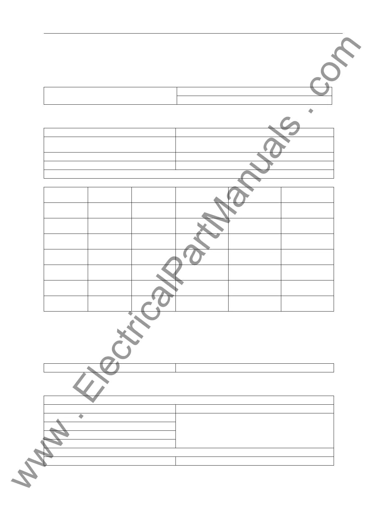
Connection modules for protection data interface, depending on the ordering version:
Module in the
Device
Connector Type Fibre Type Optical
wavelength
Perm. path
attenuation
Distance, maximum
FO5
1)
ST Multimode
62.5/125µm
820 nm 8 dB 1.5 km (0.93 miles)
FO6
2)
ST Multimode
62.5/125µm
820 nm 16 dB 3.5 km (2.2 miles)
FO7
1)
ST Monomode
9/125 µm
1300 nm 7 dB 10 km (6.25 miles)
FO8
1)
FC Monomode
9/125 µm
1300 nm 18 dB 35 km (22 miles)
FO17
1)
LC Monomode
9/125 µm
1300 nm 13 dB 24 km
FO18
1)
3)
LC Monomode
9/125 µm
1300 nm 29 dB 60 km (37.5 miles)
FO19
1)
3)
LC Monomode
9/125 µm
1550 nm 29 dB 100 km (62.5 miles)
- Character Idle State „Light off“
Direct connection:
Transmission rate 512 kbit/s
Fibre type
Refer to table above
Optical wavelength
Permissible link signal attenuation
Transmission distance
Connection via communication networks:
Communication converter See Appendix A.1, Subsection Accessories
www . ElectricalPartManuals . com
 Loading...


