3 Mounting and Commissioning
484
7SD5 Manual
C53000-G1176-C169-1
3.3.5 Checking the Protection Data Topology
General The communication topology can either be checked from the PC using DIGSI
®
or a
Web browser via the „WEB-Monitor“. If you choose to work with the „WEB-Monitor“,
please note the Help files referring to the „WEB-Monitor“.
You can either connect the PC to the device locally using the operator interface at the
front, or the service interface at the back of the PC (Figure 3-21). Or you can log into
the device using a modem via the service interface (example in Figure 3-22).
If you use the „WEB-Monitor“:
• Make sure that the 12-digit IP address valid for the browser is set correctly in the
format ***.***.***.***. A three-digit block of the IP address is inserted into each
address from 4401 to 4404, or 4411 to 4414.
• Set the address 4405 or 4415 NUM LOCK toNO , if you are directly interfaced to the
device. You will then have the option to operate the device with the „WEB-Monitor“.
• If you are interfaced to the devices via modem you can set the address 4405 or
4415 NUM LOCK to NO. You will then have the option to access all devices with the
„WEB-Monitor“.
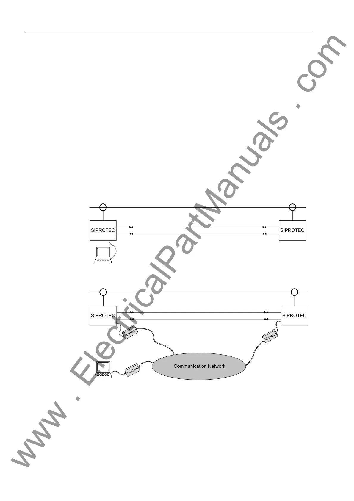
Figure 3-21 PC interfacing directly to one device — schematic example
Figure 3-22 PC interfacing via modem — schematic example
www . ElectricalPartManuals . com
 Loading...


