2.22 Monitoring Functions
381
7SD5 Manual
C53000-G1176-C169-1
2.22.1.3 Measuring Circuit Monitoring
Interruptions or short-circuits in the secondary circuits of the current and voltage trans-
formers, as well as faults in the connections (important for commissioning!), are de-
tected and reported by the device. The measured quantities are periodically checked
in the background for this purpose, as long as no system fault is present.
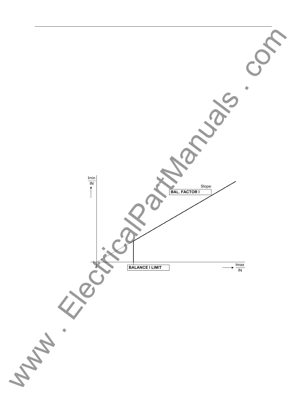
Current Symmetry During normal system operation, symmetry among the input voltages is expected. The
symmetry is monitored in the device by magnitude comparison. The smallest phase
current is compared to the largest phase current. Asymmetry is recognized if:
|I
min
| / | I
max
| < BAL. FACTOR I as long as I
max
/ I
N
> BALANCE I LIMIT / I
N
Thereby I
max
is the largest of the three phase currents and I
min
the smallest. The sym-
metry factor BAL. FACTOR I represents the allowable asymmetry of the phase cur-
rents while the limit value BALANCE I LIMIT is the lower limit of the operating range
of this monitoring (see Figure 2-164). Both parameters can be set. The dropout ratio
is about 97%.
After a settable time (5-100 s) this malfunction is signalled as „Fail I balance“
(No. 163).
Figure 2-164 Current symmetry monitoring
V o l t a g e S y m m e t r y During normal system operation (i.e. the absence of a short-circuit fault), symmetry
among the input voltages is expected. The symmetry is monitored in the device with
a magnitude comparison. The smallest phase voltage is compared to the largest.
Asymmetry is recognized if:
|U
min
| / | U
max
| < BAL. FACTOR U as long as | U
max
| > BALANCE U-LIMIT
Thereby U
max
is the largest of the three phase-to-phase voltages and U
min
the small-
est. The symmetry factor BAL. FACTOR U is the measure for the asymmetry of the
conductor voltages; the limit value BALANCE U-LIMIT is the lower limit of the oper-
ating range of this monitoring (see Figure 2-165). Both parameters can be set. The
dropout ratio is about 97%.
After a settable time, this malfunction is signalled as „Fail U balance“ (No. 167).
www . ElectricalPartManuals . com
 Loading...


