2 Functions
168
7SD5 Manual
C53000-G1176-C169-1
2.6 Power Swing Detection (optional)
The 7SD5 has an integrated power swing supplement which allows both the blocking
of trips by the distance protection during power swings (power swing blocking) and the
calculated tripping during unstable power swings (out-of-step tripping). To avoid un-
controlled tripping, the distance protection devices are supplemented with power
swing blocking functions. At particular locations in the system, out-of-step tripping
devices are also applied to split the system into islanded networks at selected loca-
tions, when system stability (synchronism) is lost due to severe (unstable) power
swings.
2.6.1 Method of Operation
Following dynamic events such as load jumps, short-circuits, reclose dead times or
switching actions it is possible that the generators must realign themselves, in an os-
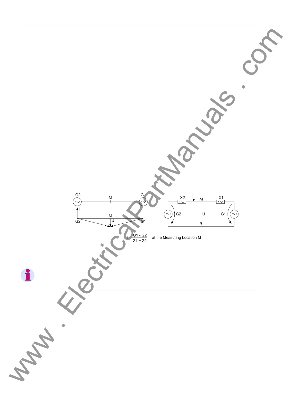
cillatory manner, with the new load balance of the system. The distance protection reg-
isters large transient currents during the power swing and, especially at the electrical
centre, small voltages (Figure 2-60). Small voltages with simultaneous large currents
apparently imply small impedances, which again could lead to tripping by the distance
protection. In expansive networks with large transferred power, even the stability of the
energy transfer could be endangered by such power swings.
Figure 2-60 Power swing
Note
The power swing supplement works together with the impedance pickup and is only
available in this combination.
System power swings are three-phase symmetrical processes. Therefore in general a
certain degree of measured value symmetry may be assumed. System power swings
may however also occur during unsymmetrical processes, e.g. during two-phase
short-circuits or during single-pole dead times. The power swing detection in the 7SD5
is therefore based on three measuring systems. For each phase, a dedicated measur-
ing system is available. Even if a power swing has been detected, any subsequent
short-circuits will result in the fast cancellation of the power swing block in the affected
phases, thereby allowing the tripping of the distance protection.
To detect a power swing, the rate of change of the impedance vectors is measured.
The message is triggered when the impedance vector enters the power swing mea-
suring range PPOL (refer to Figure 2-61) and the other criteria of power swing detec-
www . ElectricalPartManuals . com
 Loading...


