2.13 Instantaneous High-Current Switch-onto-Fault Protection (SOTF)
267
7SD5 Manual
C53000-G1176-C169-1
long lines with small source impedance. In other cases it is set to ∞ (default setting).
This parameter can only be altered with DIGSI
®
under Additional Settings.
When using a PC and DIGSI
®
to apply the settings, these can be optionally entered
as primary or secondary values. If secondary quantities are used, all currents must be
converted to the secondary side of the current transformers.
Exemplary calculation
:
110 kV overhead line 150 mm
2
with the data:
s (length) = 60 km
R
1
/s = 0.19 Ω/km
X
1
/s = 0.42 Ω/km
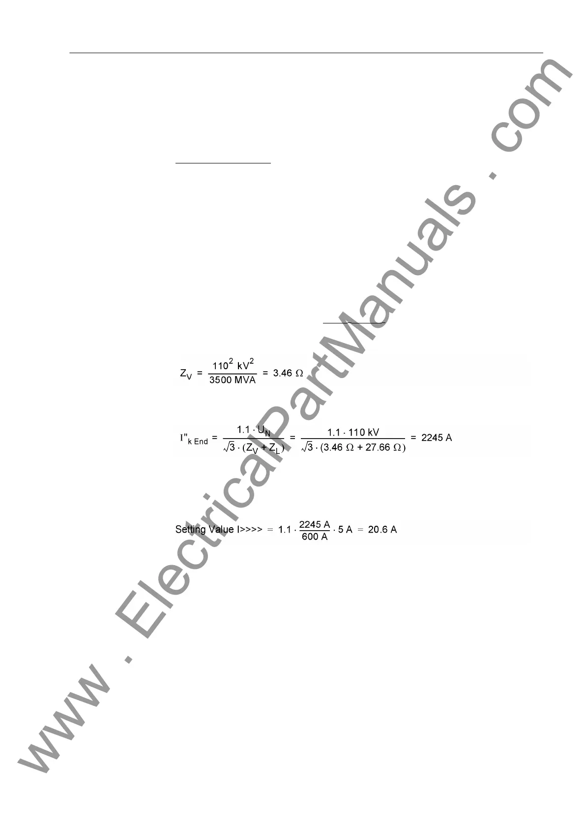
Short-circuit power at the feeding end:
S
sc
" = 3.5 GVA (subtransient, since the I>>>> stage can respond to the first peak
value)
Current transformers 600 A/5 A
From that the line impedance Z
L
and the source impedance Z
S
are calculated:
Z
1
/s = √ 0 ,19
2
+ 0,42
2
Ω/km = 0,46 Ω/km
Z
L
= 0,46 Ω/km · 60 km = 27,66 Ω
The three-phase short-circuit current at line end is I"
sc end
(with source voltage 1.1
U
N
):
With a safety factor of 10 %, the following primary setting value results:
Setting value I>>>> = 1.1 · 2245 A = 2470 A
Or the secondary setting value:
i.e. in case of fault currents exceeding 2470 A (primary) or 20.6 A (secondary) you can
be sure that a short-circuit has occurred on the protected line. This line can be discon-
nected immediately.
Note: The calculation was carried out with absolute values, which is sufficiently
precise for overhead lines. A complex calculation is only needed if the angles of the
source impedance and the line impedance vary considerably.
2.13.3 Settings
Addresses which have an appended "A" can only be changed with DIGSI, under Ad-
ditional Settings.
The table indicates region-specific presettings. Column C (configuration) indicates the
corresponding secondary nominal current of the current transformer.
www . ElectricalPartManuals . com
 Loading...


