4.19 Fault Locator
565
7SD5 Manual
C53000-G1176-C169-1
4.19 Fault Locator
1)
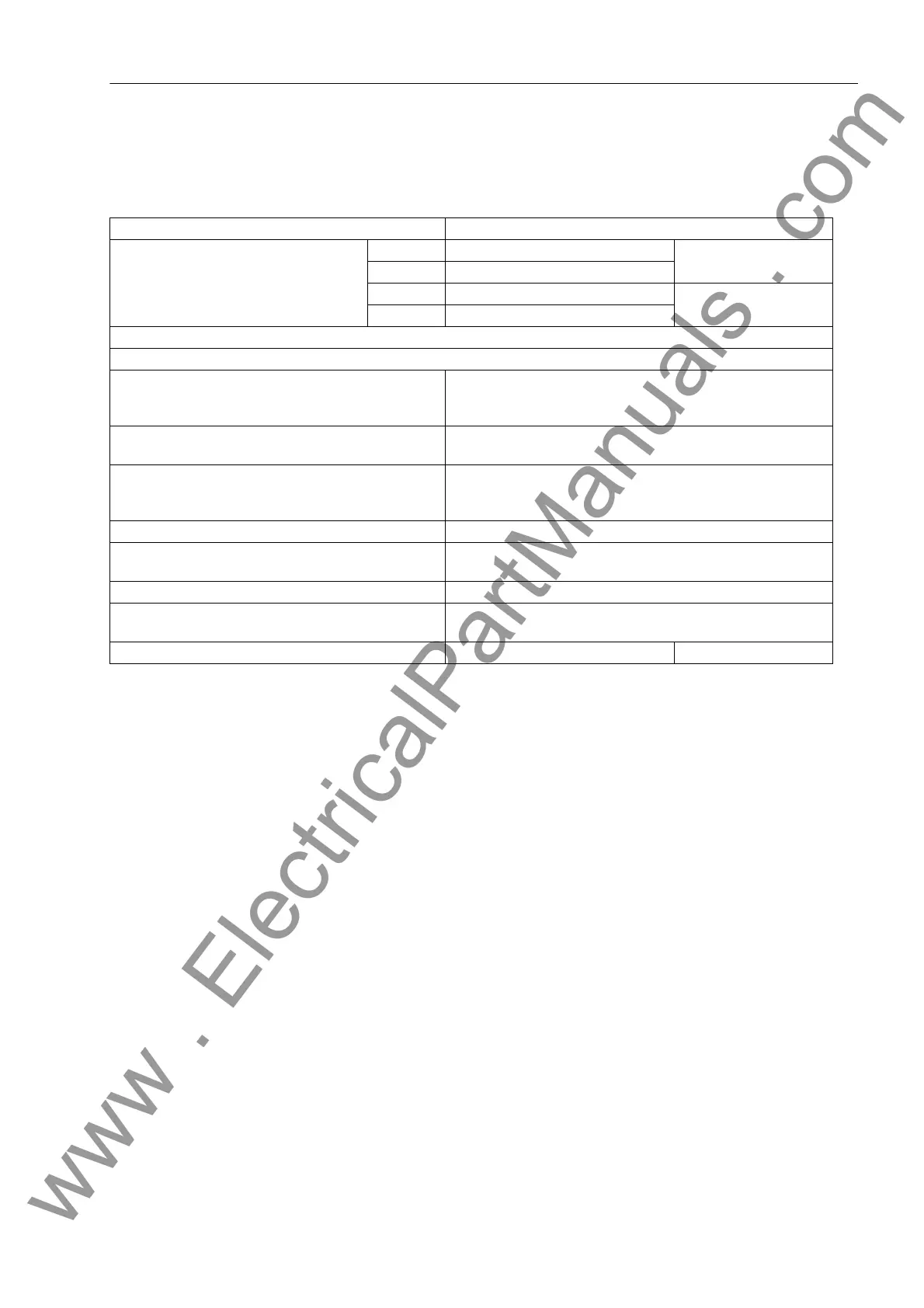
Output of the fault distance in km, miles, and % requires homogeneous lines or correctly configured line sections
Start With trip command or dropout
Reactance Setting (secondary)
in Ω/km or Ω/mile
for I
N
= 1 A 0.0050 Ω/km to 9.5000 Ω/km Increments 0.001 /km
for I
N
= 5 A 0.0010 Ω/km to 1.9000 Ω/km
for I
N
= 1 A 0.0050 Ω/mile to 15.0000 Ω/mile Increments 0.001 Ω/mile
for I
N
= 5 A 0.0010 Ω/mile to 3.0000 Ω/mile
The other settings can be found in the Power System Data 2.
When configuring mixed lines, the reactance per unit length must be set for each line section (A1 to A3)
Parallel line compensation (optional) Can be switched on/off
The setting values are the same as for distance protection (see
Section 4.5)
Taking into consideration the load current in case of
single-phase earth faults
Correction of the X-value (can be enabled and disabled)
Output of the fault distance In Ω primary and Ω secondary,
in km or miles line length
1)
in % of the line length
1)
Double-ended fault locating Can be switched on/off
Measuring tolerances
with sinusoidal quantities
2.5 % of the line length
at 30° ≤ ϕ
k
≤ 90° and U
k
/U
N
≥ 0.1
Quality index (double-ended fault location) 0 to 10 (= maximum accuracy)
Other output options (depending on order variant) as BCD–code: 4 bit units + 4 bit tens + 1 bit hundreds + data
valid bit
- BCD output time 0.01 s to 180.00 s; ∞ Increments 0.01 s
www . ElectricalPartManuals . com
 Loading...


