2 Functions
176
7SD5 Manual
C53000-G1176-C169-1
munication networks or dedicated cables (control cable or twisted phone wire). The
send and receive signals must in this case be assigned to fast command channels of
the protection data interface (DIGSI matrix).
The pilot wire comparison, that is exclusively applied to short lines, enables the user
to operate a pilot wire pair (pilot wires or control wires) with direct current to guarantee
the exchange of information between the line ends. Also the reverse interlocking op-
erates with DC control signals.
7SD5 allows also the transmission of phase-selective signals. This presents the ad-
vantage that dependable single-pole automatic reclosure can be carried out even
when two single-phase faults occur on different lines in the system.
The signal transmission schemes are also suited to three terminal lines (teed feeders).
In this case, a signal is transmitted from each of the three ends to each of the others
in both directions.
During disturbances in the transmission path, the teleprotection supplement may be
blocked without affecting the normal time graded distance protection. The measuring
reach control (enable zone Z1B) can be transmitted from the internal automatic
reclose function or via the binary input „>Enable ARzones“ from an external reclo-
sure device. With conventional signal transmission schemes, the disturbance is sig-
nalled by a binary input, with digital communication it is detected automatically by the
protection device.
2.7.2 Method of Operation
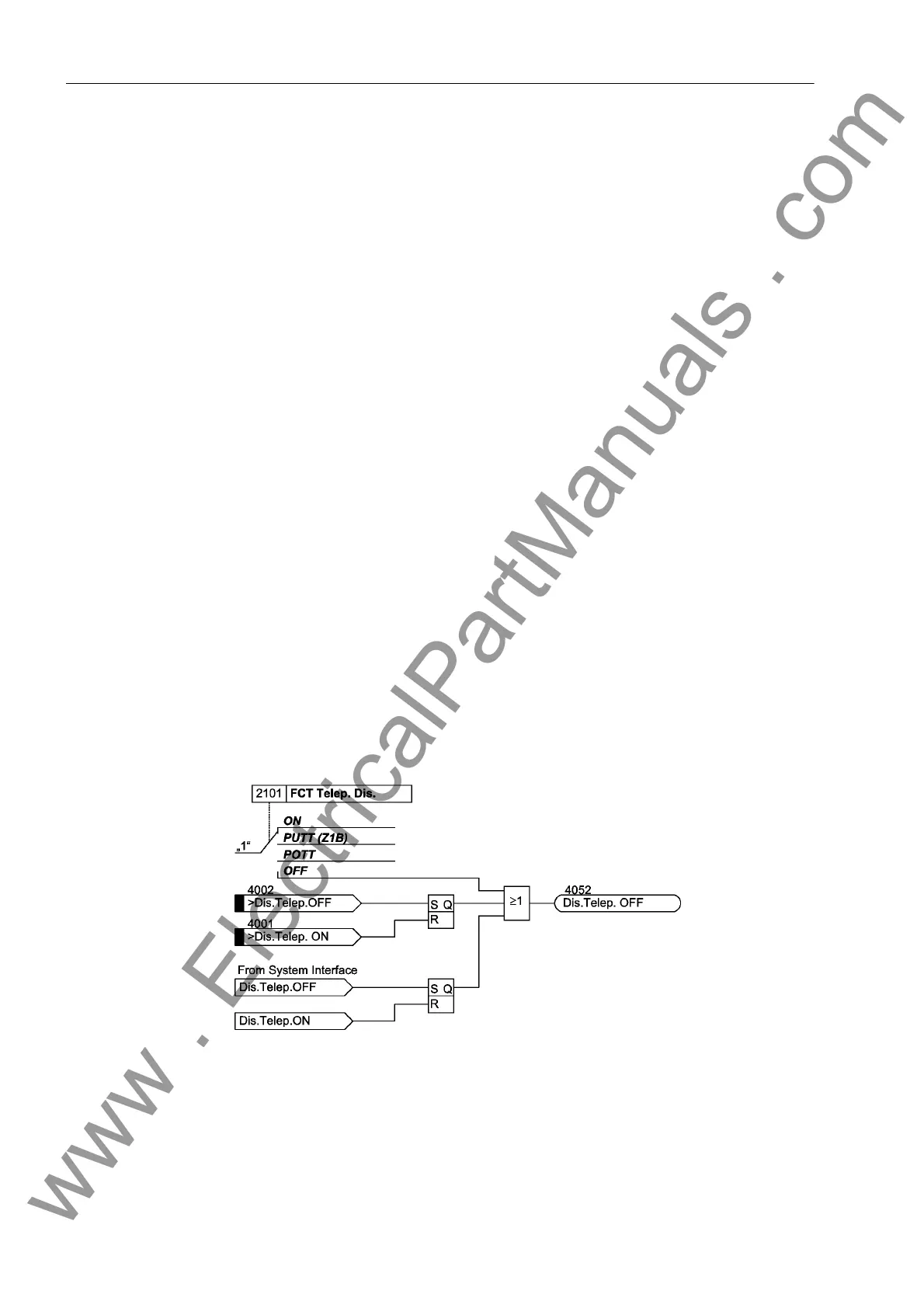
Activation and De-
activation
The teleprotection function can be switched on and off by means of the parameter
2101 FCT Telep. Dis., via the system interface (if available) or via binary input (if
this is allocated). The switched state is saved internally (refer to Figure 2-66) and
secured against loss of auxiliary supply. It is only possible to switch on from the source
where previously it had been switched off from. To be active, it is necessary that the
function is switched on from all three switching sources.
Figure 2-66 Activation and deactivation of teleprotection
www . ElectricalPartManuals . com
 Loading...


