2 Functions
352
7SD5 Manual
C53000-G1176-C169-1
device and the current input I
4
must be configured accordingly during the setting of the
General Power System Data (Power System Data 1) (Section 2.1.2.1
under „Current Transformer Connection“).
The parallel line compensation only applies to faults on the protected feeder. For ex-
ternal faults, including those on the parallel line, compensation is impossible.
Correction of Mea-
sured Values for
Load Current on
Double-end Fed
Lines (Single-
ended Fault Loca-
tor)
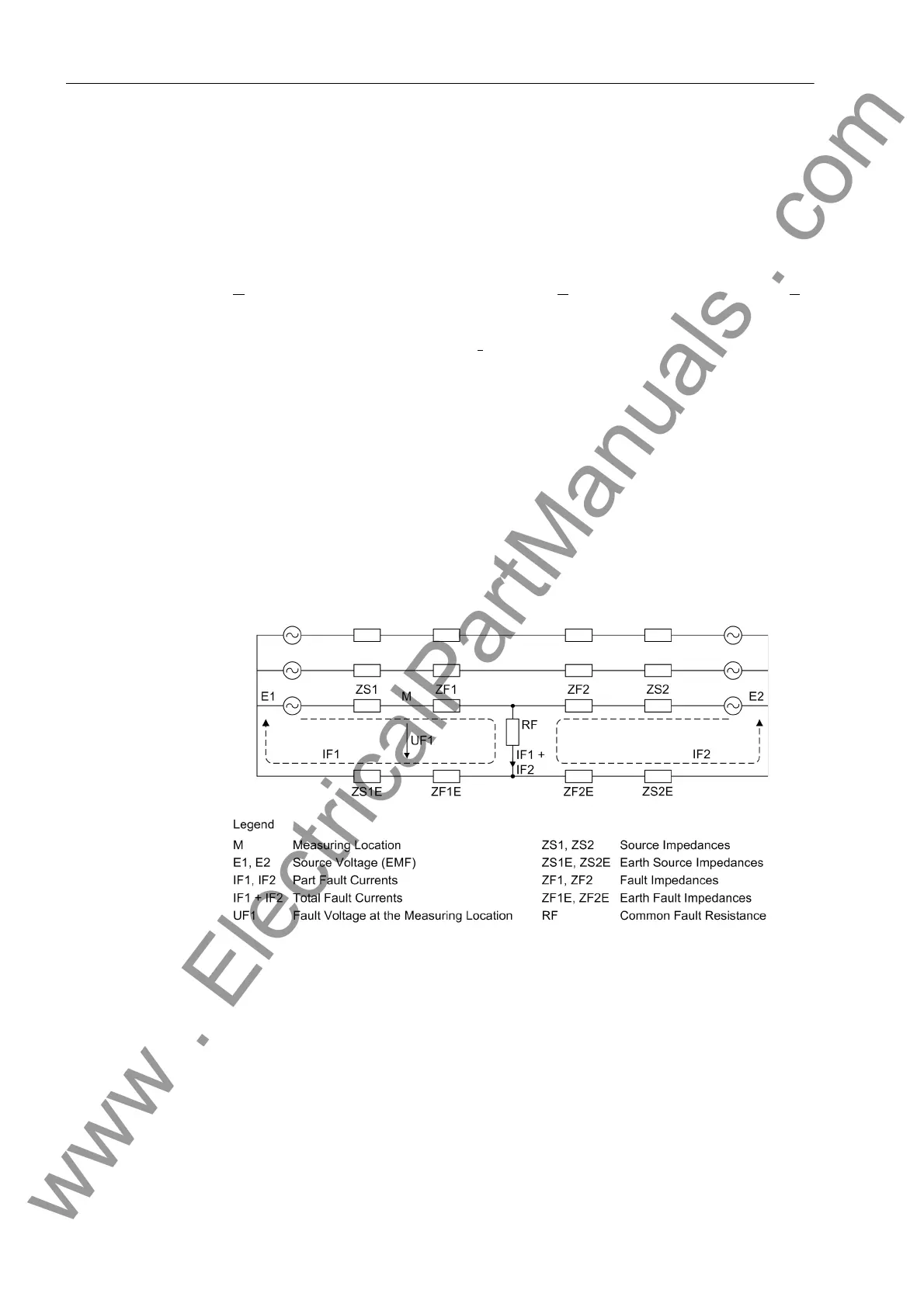
When faults occur on loaded lines fed from both ends (Figure 2-142), the fault voltage
U
F1
is influenced not only by the source voltage E
1
, but also by the source voltage E
2
,
when both voltages are applied to the common earth resistance R
F
. This causes mea-
suring errors in the result of the impedance computation unless special measures are
taken, since the current component I
F2
cannot be seen at the measuring point M. For
long heavily loaded lines, this can give a significant error in the X–component of the
fault impedance (the determining factor for the distance calculation).
For single-ended fault location calculation, a load compensation feature is provided in
the 7SD5 which corrects this measurement inaccuracy. Correction for the R–compo-
nent of the fault impedance is not possible; but the resultant inaccuracy is not critical,
since only the X–component is critical for the distance to fault indication.
Load compensation is effective for single–phase faults. For single–phase to earth
faults, positive and zero phase sequence components of the symmetrical components
are used in the compensation.
Load compensation can be switched on or off. Off-switching is useful, for example,
during relay testing, in order to avoid influences caused by the test quantities.
Figure 2-142 Fault currents and voltages on double–end fed lines
2.19.2 Setting Notes
General The fault location function is only in service if it was selected to Enabled during the
configuration of the device functions (Section 2.1.1.3, address 138).
In address 160 L-sections FL you can set the number of line sections. If you set
the number to 2 Sections or 3 Sections, a number of additional tabs for setup
will appear in DIGSI. The default setting of this address is 1 Section, which means
www . ElectricalPartManuals . com
 Loading...


