2.19 Fault Locator
355
7SD5 Manual
C53000-G1176-C169-1
If the parallel line compensation is used, set address 3805 Paral.Line Comp to YES
(presetting for devices with parallel line compensation). Further prerequisites are that
• the earth current of the parallel line has been connected to the fourth current input
I
4
with the correct polarity and
• the current transformer ratio I4/Iph CT (address 221) in the Power System Data
1 has been set correctly (refer also to Section 2.1.2.1 under „Current Transformer
Connection“) and
• the parameter for the fourth current input I4 transformer has been set to In
paral. line (address 220) in the Power System Data 1 (Section 2.1.2.1 under
„Current Transformer Connection“) and
• the mutual impedances RM/RL ParalLine and XM/XL ParalLine (addresses
1126 and 1127) have been set correctly in the general protection data (plant data
2, Section 2.1.4.1).
If load compensation is applied to single-phase faults in double-fed lines of an earthed
system, set 3806 in address Load Compensat. YES. In case high fault resistances
are expected for single-phase faults, e.g. at overhead lines without overhead earth
wire or unfavourable footing of the towers, this will improve the accuracy of the dis-
tance calculation.
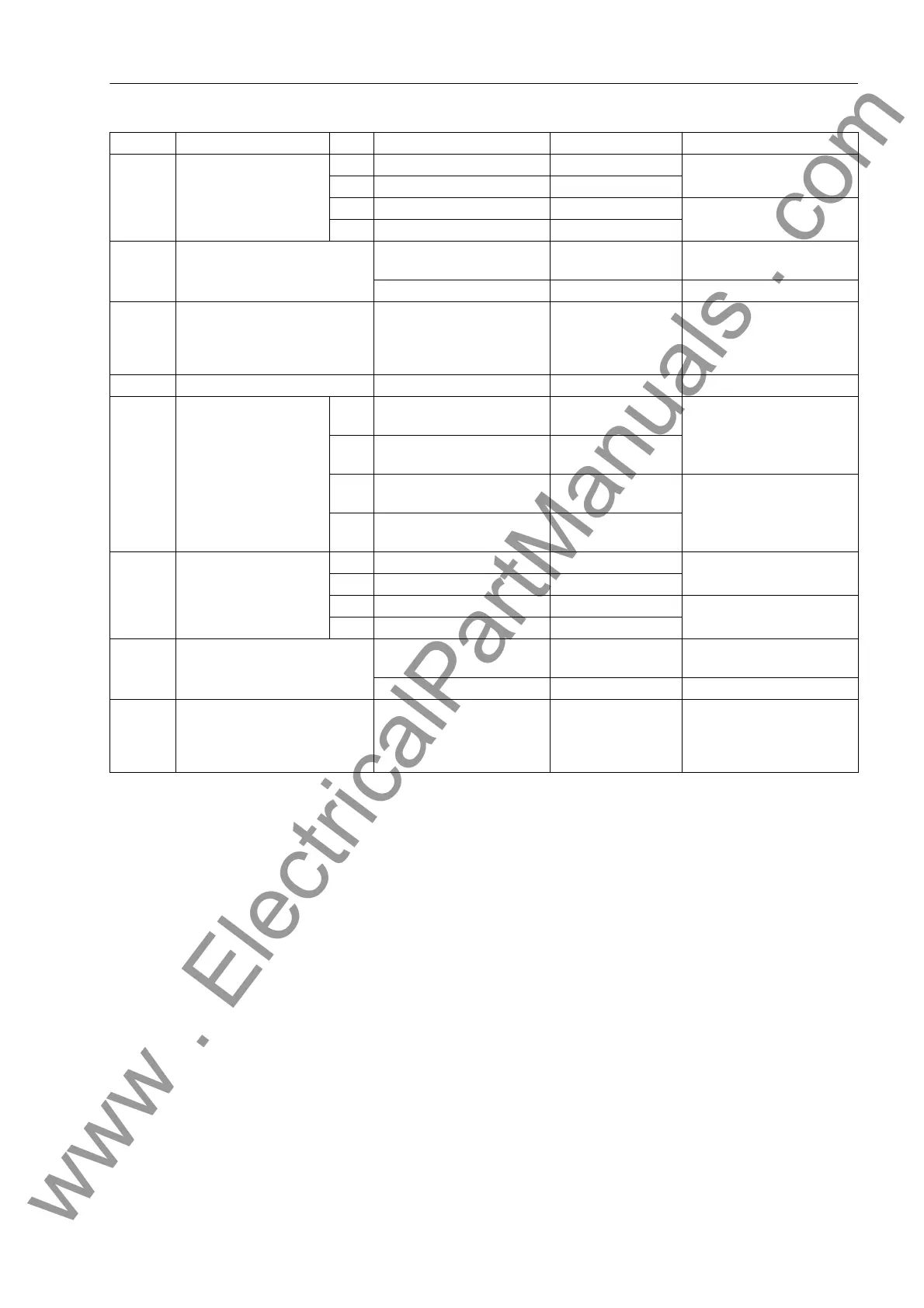
6023 S2: c' 1 A 0.000-500.000 µF/km; 0 0.050 µF/km A2: Capacitance per unit
length C' in µF/km
5 A 0.000-100.000 µF/km; 0 0.010 µF/km
1 A 0.000-800.000 µF/mi; 0 0.080 µF/mi A2: Capacitance per unit
length C' in µF/mile
5 A 0.000-160.000 µF/mile; 0 0.016 µF/mile
6024 S2: Line length 0.1-1000.0 km; ohne 0 100.0 km A2: Line length in kilome-
ters
0.1-650.0 Miles; ohne 0 62.1 Miles A2: Line length in miles
6028 S2: center ph. unknown/sym.
Phase 1
Phase 2
Phase 3
unknown/sym. A2: Central phase
6041 S3: Line angle 30-89 °; ohne 0 85 ° A3: Line impedance angle
6042 S3: x' 1 A 0.0010-1.9000 Ω/km; ohne
0
0.0300 Ω/km A3: Line reactance per unit
length: x' in Ω/km
5 A 0.0050-9.5000 Ω/km;
without 0
0.1500 Ω/km
1 A 0.0010-3.0000 Ω/mi; ohne
0
0.0484 Ω/mi A3: Line reactance per unit
length: x' in Ω/mile
5 A 0.0050-15.0000 Ω/mile;
without 0
0.2420 Ω/mile
6043 S3: c' 1 A 0.000-500.000 µF/km; 0 0.050 µF/km A3: Capacitance per unit
length C' in µF/km
5 A 0.000-100.000 µF/km; 0 0.010 µF/km
1 A 0.000-800.000 µF/mi; 0 0.080 µF/mi A3: Capacitance per unit
length C' in µF/mile
5 A 0.000-160.000 µF/mile; 0 0.016 µF/mile
6044 S3: Line length 0.1-1000.0 km; ohne 0 100.0 km A3: Line length in kilome-
ters
0.1-650.0 Miles; ohne 0 62.1 Miles A3: Line length in miles
6048 S3: center ph. unknown/sym.
Phase 1
Phase 2
Phase 3
unknown/sym. A3: Central phase
Addr. Setting Title C Setting Options Default Settings Description
www . ElectricalPartManuals . com
 Loading...


