3 Mounting and Commissioning
450
7SD5 Manual
C53000-G1176-C169-1
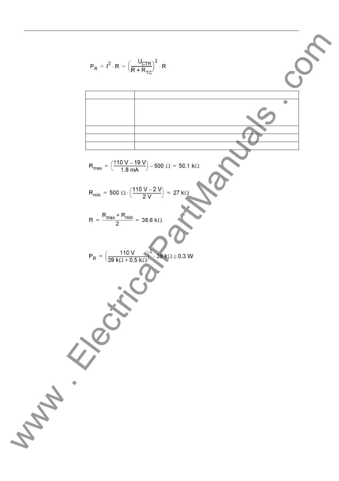
For the power consumption of the resistance:
Example:
The closest standard value of 39 kΩ is selected; the power is:
Pilot Wires for
Protection
If the distance protection is supplemented with the transmission scheme Teleprot.
Dist. = Pilot wire comp (address 121), it has to be secured that the quiescent
state loop is supplied with enough auxiliary voltage. The function itself is described in
section 2.7.
Please take note that both binary inputs are interconnected and connected in series
with the resistor of the pilot wires. Therefore the loop voltage must not be too low and
the pickup voltage of the binary inputs must not be too high. In general, the lowest
threshold (19 V) must be selected for the auxiliary voltages of 60 V to 125 V, the
threshold of 88 V is selected for voltages of 220 V to 250 V.
Due to the low current consumption of the binary inputs it may be necessary to addi-
tionally burden the pilot wire loop with an external shunt connected resistor so that the
binary inputs are not blocked by the charge of the pilot wire after an interruption of the
loop. As an alternative, auxiliary relay combinations (e.g. 7PA5210-2A) can be intro-
duced.
Pilot wires used as cable connections between stations must always be checked on
their effect on high voltage. The pilot wires of the pilot cables must stand external
strains.
The worst electrical fault that may occur to the pilot cables is generated in the pilot wire
system by an earth fault. The short-circuit current induces a longitudinal voltage into
the pilot wires lying parallel to the high voltage line. The induced voltage can be
I
BI (HIGH)
1.8 mA ( from SIPROTEC
®
4 7SD5)
U
BI min
19 V for delivery setting for nominal voltages of 24/48/60 V (from the
7SD5);
88 V for delivery setting for nominal voltages of 110/125/220/250 V (from
7SD5);
U
CTR
110 V (system / trip circuit)
R
TC
500 Ω (system / trip circuit)
U
TC (LOW)
2 V (system / trip circuit)
www . ElectricalPartManuals . com
 Loading...


