WORKSHOP MANUAL
EDITION
PAGE
118 /
124
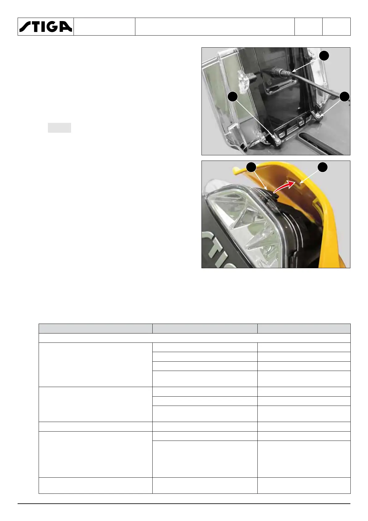
3. Disconnect the connector (2).
4. Undo the two screws (3) and remove the entire
light (4).
The light is available as a spare part
and as an assembled element, therefore it’s
not possible to disassemble it and replace in-
dividual components.
When assembling, perform the steps described
above in reverse order, taking care to correctly
insert all the tabs (5) in their respective seats (6).
10 A fuse blown
• Low coil resistance • Replace the clutch
• Faulty battery • Replace the battery
• Faulty charging system • Repair or replace.
• Faulty wiring or connections of the
PTO switch
• Check, repair or replace
Low supply voltage (less than 12 VDC
to the clutch)
• Faulty battery • Replace the battery
• Faulty charging system • Repair or replace.
• Faulty wiring or connections of the
PTO switch
• Check, repair or replace
Incorrect resistance values • Damaged winding • Replace the clutch
Inadequate power supply
• Clutch cables broken • Repair or replace.
• Faulty electrical system
• Measure the clutch coil resist-
ance and the voltage supply. If
both are correct, the electrical
system is defective. Repair or
replace.
Excessive backlash between rotor and
armature
• End of the clutch life • Replace the clutch
 Loading...