WORKSHOP MANUAL
PARK
Chapter
8 - HYDRAULIC SYSTEM
EDITION
2020
PAGE
98 /
124
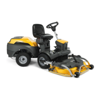
8.4.2 Valve disassembly
NOTE The valve must be removed with the by-
pass open.
1. Loosen the two nuts (1) of the elbow fitting, ap-
propriately collecting the oil still present in the
pipes.
2. Unscrew the balance valve (2).
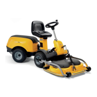
IMPORTANT Each balancing valve (2) is
equipped with a code punched on one face of
the hexagon. This code identifies the valve mod-
el, which is different for each type of machine
and is essential for any spare parts request.
8.4.3 Valve calibration
The dynamic balancing valve has a standard setting of 0.15 mm; this value can be adjusted in the
range ± 0.05 mm with respect to the standard calibration.
● With the dynamic balancing valve set at 0.10 mm, the valve closing time is reduced, which
means an increase in the traction performance at the expense of smooth steering.
● With the dynamic balancing valve set at 0.20 mm, the valve closing time increases, which
means an increase in the fluidity of the steering at the expense of traction performance.
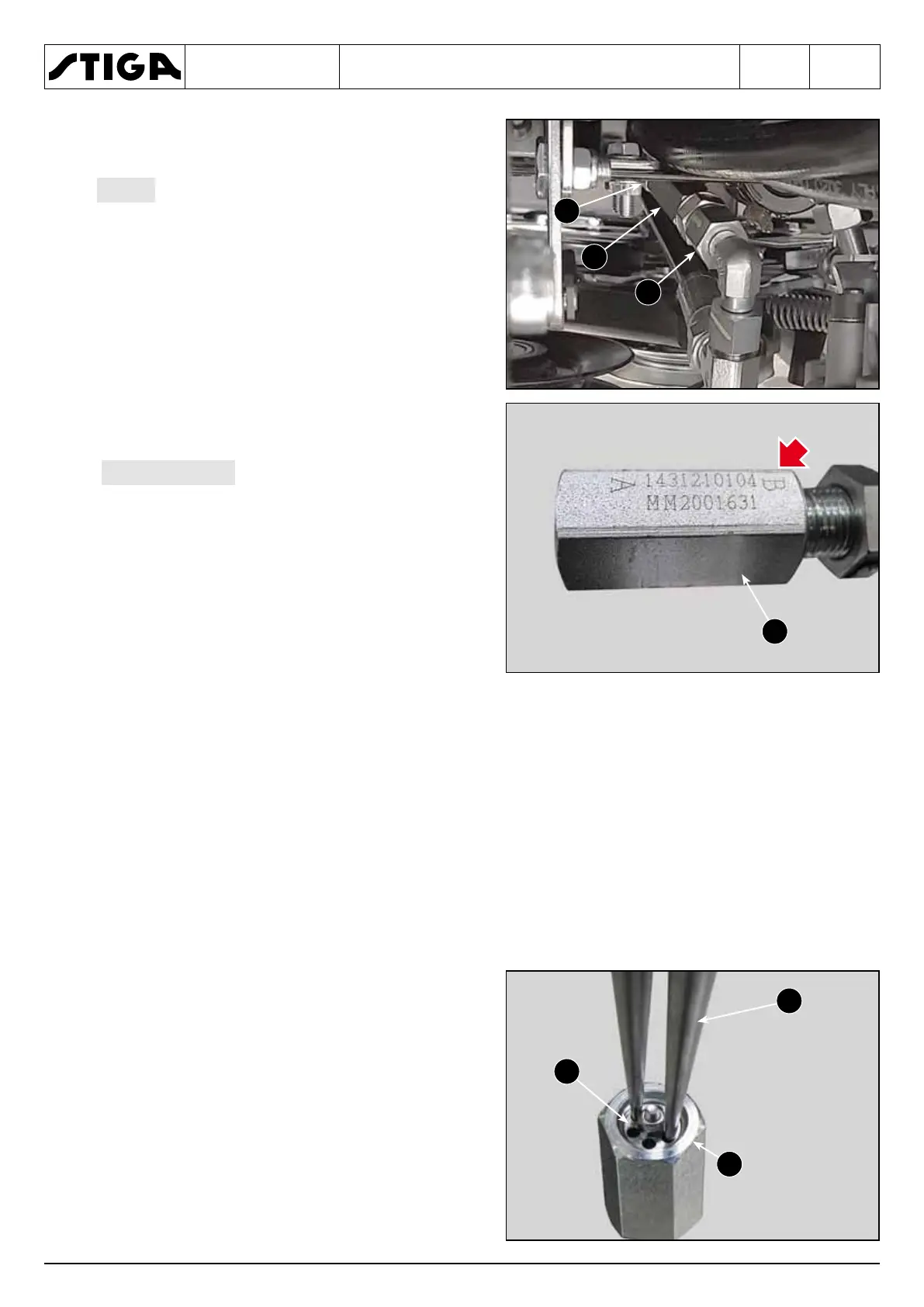
To change the calibration, it is necessary to dis-
assemble the valve and act as follows.
1. Secure the valve body (1) in a vice and un-
screw the internal valve (2) with the help of
long needle nose pliers (3) or a special tool.
3
2
1
2
1
2
1
 Loading...