Reelmaster 7000−D Page 6 − 3 Electrical System
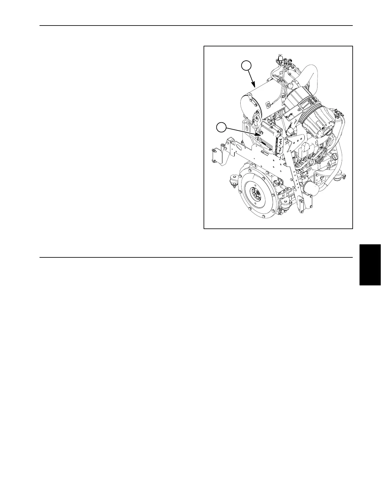
Engine Electronic Control Unit (ECU) (Yanmar Diesel Engines Only)
The Yanmar engine that powers the Reelmaster
7000−D (Model 03780/03780A) uses an electronic con-
trol unit (ECU) for engine management and also to com-
municate with the Toro Electronic Controller (TEC) and
the InfoCenter Display on the machine. All engine ECU
electrical connectors should be plugged into the control-
ler before the machine ignition switch is moved to either
the ON or START position. If the engine ECU is to be dis-
connected for any reason, make sure that the ignition
switch is in the OFF position with the key removed be-
fore disconnecting the engine ECU. See Chapter 3 −
Yanmar Diesel Engine for additional engine ECU in-
formation.
IMPORTANT: Do not plug or unplug the engine ECU
for a period of thirty (30) seconds after the machine
ignition switch is turned OFF. The ECU may remain
energized even though the ignition switch is OFF.
Figure 1
1. Yanmar engine 2. Engine ECU
1
2
CAN−bus Communications
The Toro Electronic Controller (TEC) used on the Reel-
master 7000−D can communicate with other electrical
components (engine ECU and InfoCenter display) on a
CAN−bus communication system. The CAN−bus sys-
tem reduces the number of electrical components and
connections used on the machine and allows the num-
ber of wires in the wire harness to be reduced.
CAN identifies the Controller Area Network that is used
on the Reelmaster. Two (2) specially designed, twisted
cables form the bus. These wires provide the data path-
ways between machine components. The engineering
term for these two (2) cables are CAN−high and CAN−
low. At the ends of the twisted pair of bus cables are 120
ohm termination resistors.
Each of the components that is controlled by the CAN−
bus link only needs four (4) wires to operate and commu-
nicate to the system: CAN−high, CAN−low, B+ (power)
and ground.
IMPORTANT: The termination resistors at the ends
of the bus cables are required for proper electrical
system operation.
Electrical
System
 Loading...


