Reelmaster 7000−DPage 6 − 54Electrical System
Relays with Five (5) Terminals
Your Reelmaster 7000−D uses an electrical relay that
has five (5) terminals. A tag near the wire harness relay
connector can be used to identify each relay.
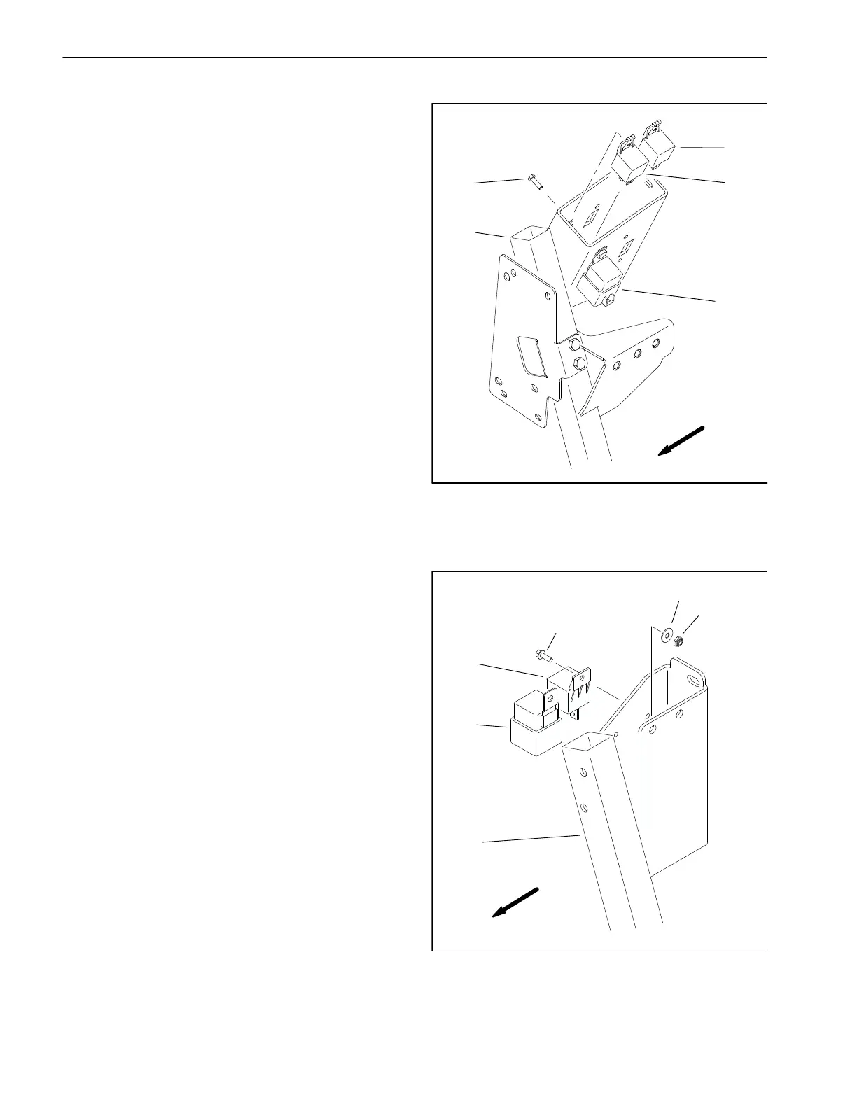
On machines with Yanmar diesel engines, an EGR relay
is used to provide current to the engine EGR valve when
energized by the engine ECU. The EGR relay is located
on the air cleaner mounting bracket (Fig. 58)
On machines with Kubota diesel engines,the start relay
is a five (5) terminal relay. The start relay is used to pro-
vide current to the engine starter motor solenoid. The
start relay is energized and monitored by the Toro Elec-
tronic Controller (TEC). The start relay is located on the
air cleaner mounting bracket (Fig. 59).
Testing
1. Park machine on a level surface, lower cutting units,
stop engine, engage parking brake and remove key
from the ignition switch.
2. To make sure that machine operation does not occur
unexpectedly, disconnect negative (−) cable from bat-
tery and then disconnect positive (+) cable from battery
(see Battery Service in this chapter).
3. Locate relay that is to be tested.
4. Disconnect wire harness connector from relay. Re-
move relay from mounting bracket for testing.
NOTE: Prior to taking small resistance readings with a
digital multimeter, short the meter test leads together.
The meter will display a small resistance value (usually
0.5 ohms or less). This resistance is due to the internal
resistance of the meter and test leads. Subtract this val-
ue from from the measured value of the component you
are testing.
5. Using a multimeter, verify that coil resistance be-
tween terminals 85 and 86 is from 71 to 88 ohms
(Fig. 60).
6. Connect multimeter (ohms setting) leads to relay ter-
minals 30 and 87. Ground terminal 86 and apply +12
VDC to terminal 85. The relay should make and break
continuity between terminals 30 and 87 as +12 VDC is
applied and removed from terminal 85.
7. Disconnect voltage from terminal 85 and multimeter
lead from terminal 87.
8. Connect multimeter (ohms setting) leads to relay ter-
minals 30 and 87A. Apply +12 VDC to terminal 85. The
relay should make and break continuity between termi-
nals 30 and 87A as +12 VDC is applied and removed
from terminal 85.
1. Air cleaner mount
2. Screw (3)
3. Start relay (4 terminal)
4. Glow relay (4 terminal)
5. EGR relay (5 terminal)
Figure 58
FRONT
4
3
2
1
5
YANMAR DIESEL ENGINE
1. Air cleaner mount
2. Start relay (5 terminal)
3. Glow relay (4 terminal)
4. Screw (2)
5. Washer (2)
6. Lock nut (2)
Figure 59
FRONT
KUBOTA DIESEL ENGINE
1
2
3
4
5
6
 Loading...


