Reelmaster 7000−DPage 6 − 22Electrical System
Using the InfoCenter Display for Troubleshooting
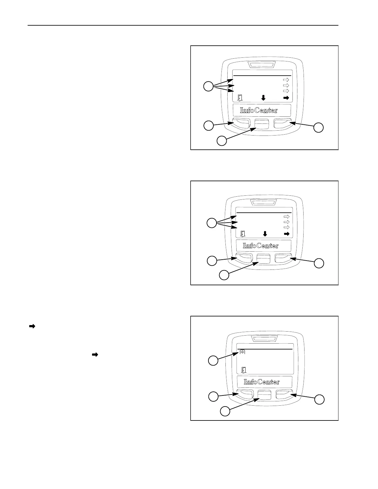
The diagnostics screen of the InfoCenter display can be
very helpful when troubleshooting machine operation is-
sues (see Diagnostics Screen in this chapter). The diag-
nostics screen (Fig. 22) lists a variety of machine
operations and the current state of the inputs, the quali-
fiers and the outputs required to allow the operation to
proceed. The electrical components involved in the fol-
lowing machine operations can be evaluated using the
diagnostics screen prior to testing each component indi-
vidually:
Lift/Lower The components necessary to raise or
lower the cutting units.
High/Low Range The components necessary to
shift the dual displacement wheel/axle motors from
LOW to HIGH speed range.
PTO The components necessary to engage the cut-
ting units.
Engine The components necessary to start and run
the engine.
Backlap The components necessary to engage the
cutting units in the reverse direction for backlapping.
If a machine operation is malfunctioning, the following
procedure can help identify the cause of the component
or circuit wiring causing the malfunction.
1. Park machine on a level surface, lower cutting units,
engage parking brake and stop engine.
2. Set the ignition switch to the ON position and navi-
gate to the InfoCenter Diagnostic Screen.
3. Select (highlight) the malfunctioning machine opera-
tion and press the Left/Right button (as indicated by the
at the bottom of the screen). For this example, the
PTO operation has been selected (Fig. 23).
4. Select (highlight) Inputs and press the Left/Right but-
ton (as indicated by the at the bottom of the screen).
5. Manually operate each input item listed (Fig. 24).
The input condition on the InfoCenter display should al-
ternate ON and OFF as the input is switched open and
closed. If ON and OFF do not alternate during input op-
eration, the input component or its circuit wiring is faulty
and should be tested (see Component Testing in this
chapter).
In the PTO operation example, the only input is the Reel
Enable/Disable switch. If ON and OFF do not alternate
when the switch is moved back and forth from ENABLE
to DISABLE, the switch or the circuit wiring for the switch
is faulty and should be tested as described.
Figure 22
1. Machine operations
2. Left/Right button
3. Down button
4. Menu/Back button
Diagnostics
Lift/Lower
High/Low Range
PTO
4
3
2
1
DIAGNOSTICS SCREEN
Figure 23
1. Diagnostics items
2. Left/Right button
3. Down button
4. Menu/Back button
PTO
Inputs
Qualifiers
Outputs
4
3
2
1
DIAGNOSTICS SCREEN (PTO SELECTED)
Figure 24
1. Input items
2. Left/Right button
3. Down button
4. Menu/Back button
PTO
Input:
4
3
2
1
DIAGNOSTICS SCREEN (PTO INPUTS SELECTED)
ON
 Loading...


