The (active) safety planes are shown in yellow and black with a small arrow representing the
plane normal, which indicates the side of the plane on which the robot TCP is allowed to be
positioned. Trigger planes are displayed in blue and green. A small arrow illustrates the side of
the plane that does not trigger the transition into Reduced mode. If a safety plane has been
selected in the panel on the left side of the tab, the corresponding 3D representation is
highlighted.
The tool orientation boundary limit is visualized with a spherical cone together with a vector
indicating the current orientation of the robot tool. The inside of the cone represents the allowed
area for the tool orientation (vector).
When a plane or the tool orientation boundary limit is configured but not active, the visualization
is gray.
Push the magnifying glass icons to zoom in/out or drag a finger across to change the view.
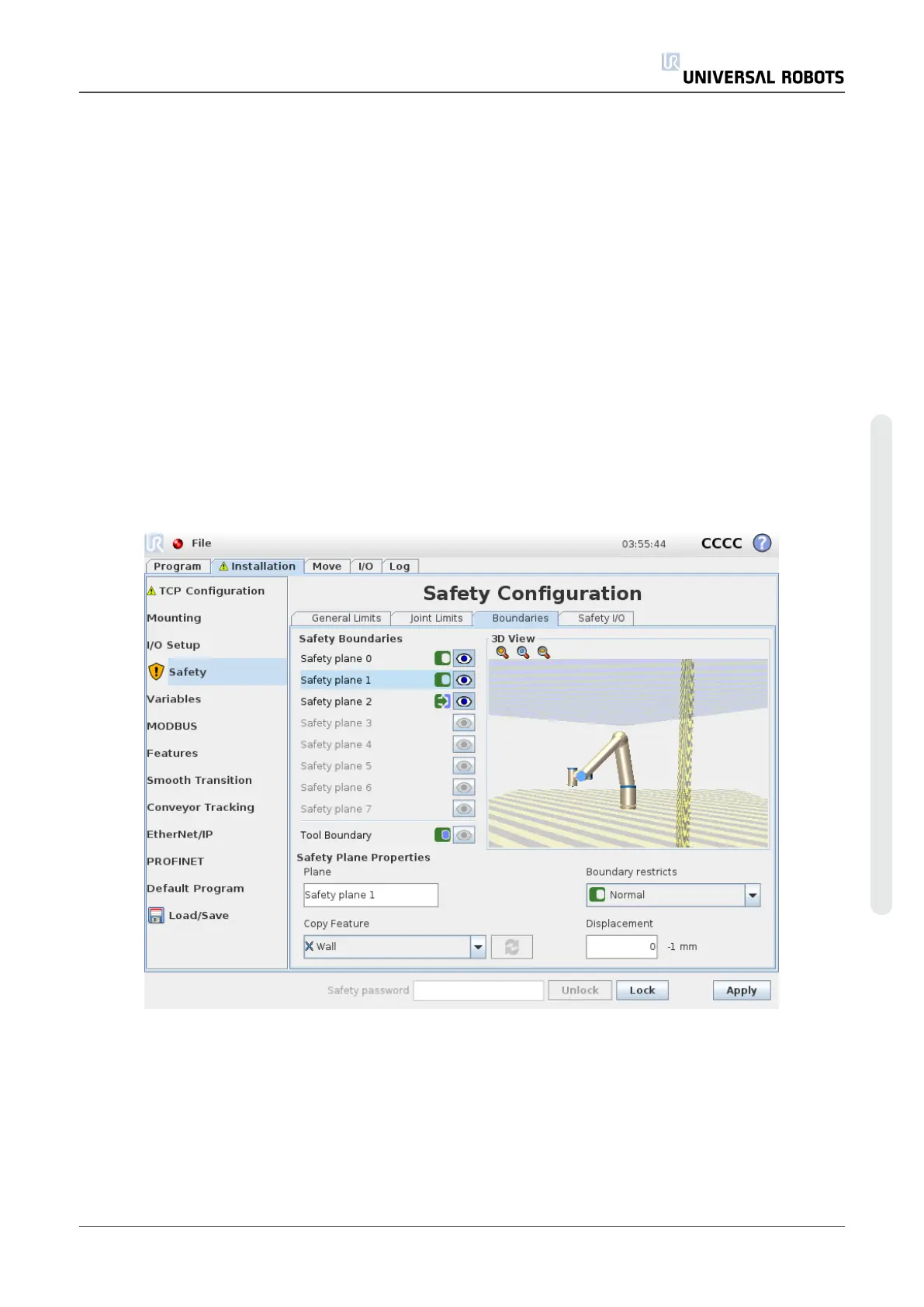
Safety plane configuration
The Safety Plane Properties section at the bottom of the tab defines the configuration of
the selected safety plane in the Safety Boundaries panel in the upper left portion of the tab.
Name
The Name text field allows the user to assign a name to the selected safety plane. Change the
name by tapping the text field and entering a new name.
User Manual 99 UR10
Copyright © 2009–2020 by UniversalRobotsA/S. All rights reserved.

 Loading...


