robot TCP is positioned 20mm or further from the Trigger Reduced mode plane (on the Normal
mode side), the Reduced mode limit set is no longer active and the Normal mode limit set is
enforced.
If the predicted trajectory takes the robot TCP through a Trigger Reduced mode plane, the robot
arm will start decelerating even before passing through the plane if it is about to exceed joint
speed, tool speed or momentum limit in the new limit set. Note that since these limits are
required to be more restrictive in the Reduced mode limit set, such premature deceleration can
occur only when transitioning from Normal to Reduced mode.
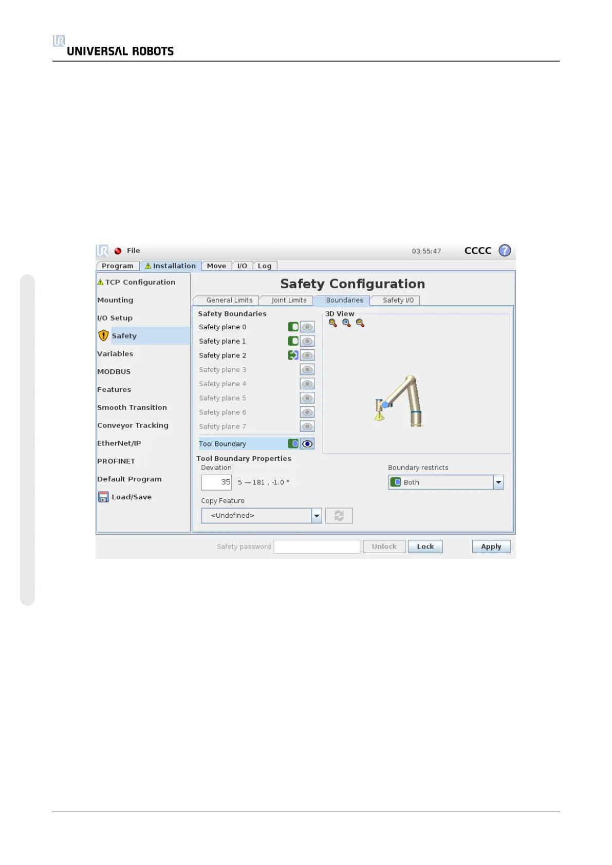
Tool Boundary configuration
The Tool Boundary Properties panel at the bottom of the tab defines a limit on the
orientation of robot tool composed of a desired tool orientation and a value for the maximum
allowed deviation from this orientation.
Deviation
The Deviation text field shows the value for the maximum allowed deviation of the orientation
of the robot tool from the desired orientation. Modify this value by tapping the text field and
entering the new value.
The accepted value range together with the tolerance and unit of the deviation are listed next to
the text field.
UR10 102 User Manual
Copyright © 2009–2020 by UniversalRobotsA/S. All rights reserved.

 Loading...


