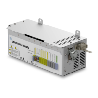
some adaptors will not connect the UR robot and your IMM correctly. It is recommended to read
both the EUROMAP 12 and EUROMAP 67 standard whenever using or constructing an adaptor.
A list with common errors is shown below:
1. Do you measure 24V between A9 and C9?
• The IMM must supply 24V to enable the I/O signals.
• If the robot and the IMM has common minus/0V then the robot 24V can be used by
connecting A9 to ZA9 and C9 to ZC9. IMM 24V is often present at EUROMAP 12 pin
32.
2. Is the adaptor switching both robot emergency channels and both robot safety devices
channels?
• This is typically accomplished using 4 relays.
WARNING
Make sure the E12 - E67 converter conforms to the EUROMAP 67 and EUROMAP
12 standards and that the safety functions are constructed with the correct
performance level. Failure to follow this warning could result in serious injury or
death as the safety function could be overridden.
1.28. GUI
The next subsections describe how the euromap interface is controlled from the GUI, how to
verify the signals to and from the IMM, how the easy programming is done with structures and
how more advanced things can be accomplished using the signals directly.
It is, though, highly recommended to use the EUROMAP 67 program template instead of making a
program from scratch, see below.
1.28.1. EUROMAP 67 program template
After installing the EUROMAP 67 interface, an extra button appears which gives access to the
EUROMAP 67 program template.
User Manual 219 UR10
EUROMAP 67 Interface
Copyright © 2009–2020 by UniversalRobotsA/S. All rights reserved.

 Loading...


