1.23. Robot Control
1.23.1. Move Tab
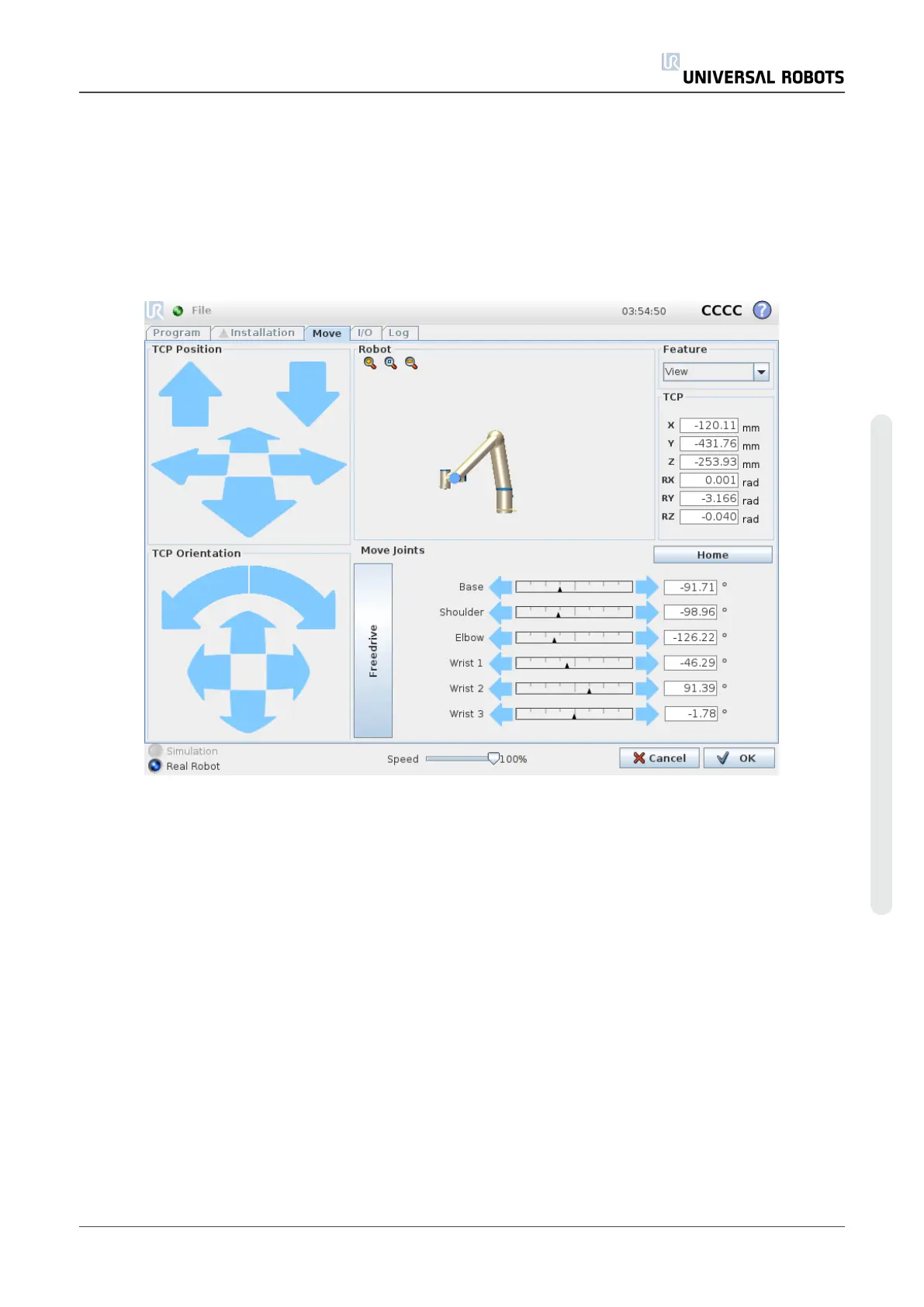
On this screen you can always move (jog) the robot arm directly, either by translating/rotating the
robot tool, or by moving robot joints individually.
Robot
The current position of the robot arm is shown in 3D graphics. Push the magnifying glass icons
to zoom in/out or drag a finger across to change the view. To get the best feel for controlling the
robot arm, select the View feature and rotate the viewing angle of the 3D drawing to match your
view of the real robot arm.
If the current position of the robot TCP comes close to a safety or trigger plane, or the orientation
of robot tool is near the tool orientation boundary limit (see 1.20.12. Boundarieson page97), a
3D representation of the proximate boundary limit is shown. Note that when the robot is running
a program, the visualization of boundary limits will be disabled.
Safety planes are visualized in yellow and black with a small arrow representing the plane
normal, which indicates the side of the plane on which the robot TCP is allowed to be positioned.
Trigger planes are displayed in blue and green and a small arrow pointing to the side of the plane,
where the Normal mode limits (see 1.20.6. Safety Modeson page91) are active. The tool
User Manual 121 UR10
Copyright © 2009–2020 by UniversalRobotsA/S. All rights reserved.

 Loading...


