Configurable outputs that are reserved for safety settings are not togglable and will be displayed
as LED’s only.
The electrical details of the signals are described in chapter1.9.3. Controller I/Oon page30.
Voltage
In Tool Output, Voltage can be configured only when Tool Output is controlled by the User.
Selecting a URCap removes access to the Voltage.
Analog Domain Settings
The analog I/O’s can be set to either current [4-20mA] or voltage [0-10V] output. The settings will
be remembered for eventual later restarts of the robot controller when a program is saved.
Selecting a URCap, in Tool Output, removes access to the Domain Settings for the analog Tool
Inputs.
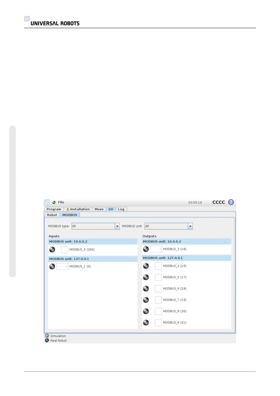
1.23.3. MODBUS
The screenshot below displays the MODBUS client I/O signals as they are set up in the
installation. Using the drop-down menus at the top of the screen, you can change the displayed
content based on signal type and MODBUS unit if more than one is configured. Each signal in the
lists contains its connections status, value, name, and signal address. The output signals can be
toggled if the connection status and the choice for I/O tab control allows it (see 1.23.8.
Installation → I/O Setupon page132).
UR10 124 User Manual
Copyright © 2009–2020 by UniversalRobotsA/S. All rights reserved.

 Loading...


