Abbreviation Meaning
MAF Moulding Area Free
A, B, C, ZA, ZB and ZC Signals inside EUROMAP 67 cable
NOTE
EUROMAP 67 is only supported on controller boxes produced after September
2014.
WARNING
An IMM can use up to 250V on some of its signals. Do not connect an IMM to the
EUROMAP 67 interface if it is not properly installed in a controller box; including
all mandatory ground connections.
WARNING
1. Make sure to install a light curtain (safety device) between the robot and
the IMM in such a way that the IMM cannot close the mould when the robot
is inside it. Failure to do so may damage both the robot and the mould.
2. Read and understand this manual completely before trying out the euromap
67 interface.
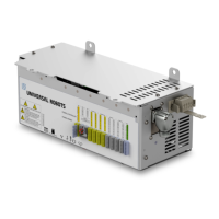
1.26.1. EUROMAP 67 standard
The EUROMAP 67 standard is free of charge and can be downloaded from www.euromap.org.
The UR EUROMAP 67 module conforms to all demands in this standard when it is powered up.
When it is powered down the EUROMAP 67 standard specifies that every safety related signal
shall be operative. This may cause hazardous situations and contradicts the safety
specifications of ISO 13849-1 and EN ISO 13849-1. Therefore, the UR EUROMAP 67 module opens
the emergency stop signals, MAF signals and all I/O signals when the controller box is powered
off.
All optional, manufacturer dependent and reserved I/O signals are supported. Interfacing
according to EUROMAP 67.1 is also possible.
1.26.2. Statutory notice
The interface is constructed with the same components and principles, and under the same test
requirements, as the control box and can only be purchased in conjunction with a control box.
The EUROMAP 67 interface therefore falls under the Declaration of Incorporation, found in the
Hardware Installation Manual .
UR10 216 User Manual
EUROMAP 67 Interface
Copyright © 2009–2020 by UniversalRobotsA/S. All rights reserved.

 Loading...


