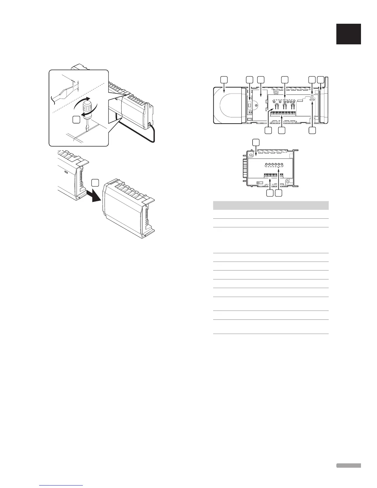
Remove the slave module
The illustration below shows how to remove the slave
module from the controller.
1
1.2 mm
8 mm
2
1. Place a wide flat head screwdriver in the slot
between the slave module and the other unit and
twist until the snap-in lock releases. Repeat for the
other side.
2. Remove the slave module. Use caution not to bend
the connection pins.
5.5 Connect components to controller
Refer to the wiring diagram found in the end of this
document. The illustration below shows the inside of
the controller.
F J
Item Description
A Transformer, 230 V AC 50 Hz power module
B Fuse (T5 F3.15AL 250 V)
C Optional inputs and outputs for pump
management, boiler management, and heat pump
connection
230 V connection from transformer
D Channel registration buttons
E LEDs for channels 01 – 06
F Quick connectors for actuators
G MicroSD card (Wave PLUS only)
H Power LED
I Uponor Smatrix Wave Slave Module M-160
(optional)
J LEDs for channels 07 – 12
K Uponor Smatrix Wave Antenna A-165, RJ-45
connector
UK
CZ
DE
DK
EE
ES
FI
FR
HR
HU
IT
LT
LV
NL
NO
PL
PT
RO
RU
SE
SK
25
UPONOR SMATRIX WAVE/WAVE PLUS
· INSTALLATION AND OPERATION MANUAL
 Loading...