12.8 H: Terminal Function Selection
676 YASKAWA SIEPC71061753C GA500 Technical Manual
When you set a terminal that is not in use to F, you can use the signal input to the terminal as PLC analog signal
input through MEMOBUS/Modbus communications or the communication option. This input signal does not
have an effect on drive operation. This functions the same as setting 1F (Through Mode).
■ 10: Forward Torque Limit
Setting Value Function Description
10 Forward Torque Limit
Enters the forward torque limit if the motor rated torque is 100%.
WARNING! Sudden Movement Hazard. Set correct torque limits for applications, for example elevator applications. If you set
torque limits incorrectly, motor torque that is not sufficient can cause damage to equipment and cause serious injury or death.
Torque Limit Configuration Method
Use one of these methods to set torque limits:
• Individually set the four torque limit quadrants using L7-01 to L7-04 [Torque Limit].
• Use MFAI to individually set the four torque limit quadrants. Set H3-02, H3-10 = 10, 11, 12 [MFAI Function
Select = Forward/Reverse/Regenerative Torque Limit].
• Use MFAI to set all four torque limit quadrants together. Set H3-02, H3-10 = 15 [General Torque Limit].
• Use a communication option to set all four torque limit quadrants together.
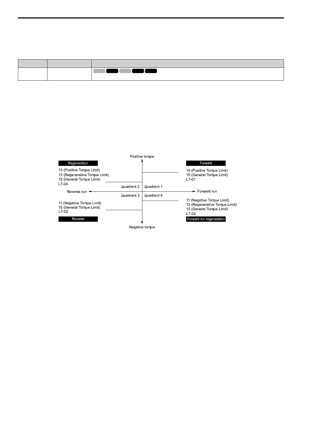
Figure 12.96 shows the configuration method for each quadrant.
Figure 12.96 Torque Limits and Analog Input Setting Parameters
Note:
• When L7-01 to L7-04 and analog inputs or communication option torque limits set torque limits for the same quadrant, the lower value
is enabled.
In this example of parameter settings, the torque limit for quadrant 1 is 130% and the torque limit for quadrants 2, 3, and 4 is 150%.
Settings: L7-01 = 130%, L7-02 to L7-04 = 200%, and MFAI torque limit = 150%
• The drive output current limits maximum output torque. The torque limit is 150% of the rated output current for HD and to 120% of
the rated output current for ND. The actual output torque is not more than the limits of the drive rated output current when you set the
torque limit to a high value.
If you use drives in applications where the vertical axis can fall, make sure that you know these items:
• Correctly configure drives and motors.
• Correctly set parameters.
• You can change parameter values after you do Auto-Tuning.
• Use a system that will not let the vertical axis fall if the drive fails.
Figure 12.97 shows the relation between torque limits from parameters and torque limits from analog input.

 Loading...


