Low Voltage Products & Systems 107
ABB Inc. • 888-385-1221 • www.abb-control.com AC 1006.9 - 5/03
Chapter 8 - Fieldbus communication (option)
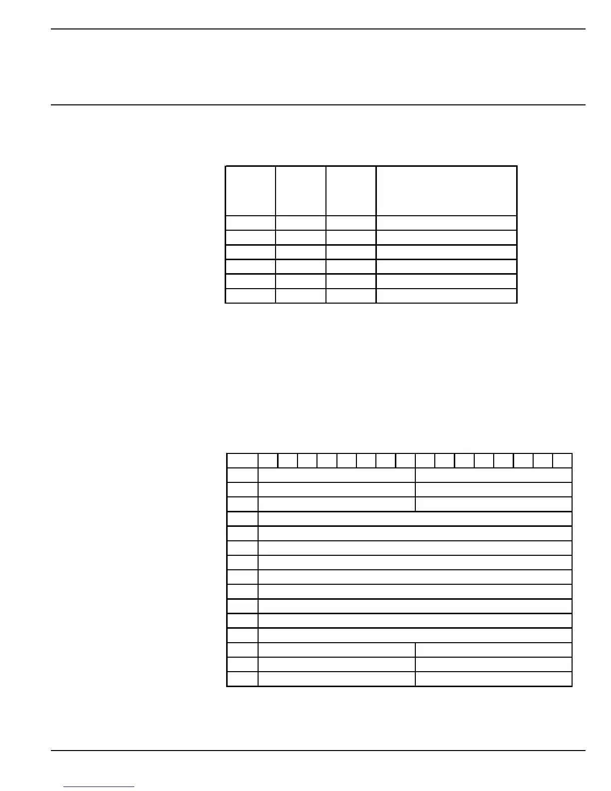
8:1.3.5 Analog output telegram
From PLC to Softstarter.
All analog data will be represented as 16 bit values.
The output data is used to synchronize the softstarter real time clock with a
system clock.
It is used together with the binary output time synchronisation signal. If this
signal is set to “1” and there is a difference between the clocks, the local
softstarter clock will be synchronised with the analog outputs.
8:1.3.6 Input address map
Word in
output
data area
Analog
output
word
Data Representation
1 0 Year Value = 2003 » Year 2003
2 1 Month Value = 12 » December
3 2 Day Value = 31 » 31st
4 3 Hour Value = 23 » 23 h
5 4 Minutes Value = 59 » 59 min
6 5 Seconds Value = 59 » 59 sec
1514131211109876543210
0
1
2
3
4
5
6
7
8
9
10
11
12
13
14
Diagn. Channel 1, Parameter No
Diagn. Channel 2, Parameter No
Diagn. Channel 3, Parameter No
Diagn. Channel 1, Error Code
Diagn. Channel 2, Error Code
Diagn. Channel 3, Error Code
Binary In, Byte 0
Binary In, Byte 2
Binary In, Byte 4
Analog In, Word 0
Analog In, Word 1
Analog In, Word 2
Analog In, Word 3
Analog In, Word 5
Analog In, Word 6
Analog In, Word 7
Analog In, Word 8
Analog In, Word 4
Binary In, Byte 1
Binary In, Byte 3
Binary In, Byte 5
 Loading...