52 Low Voltage Products & Systems
AC 1006.9 - 5/03 ABB Inc. • 888-385-1221 • www.abb-control.com
Chapter 6 - Human-Machine Interface (HMI)
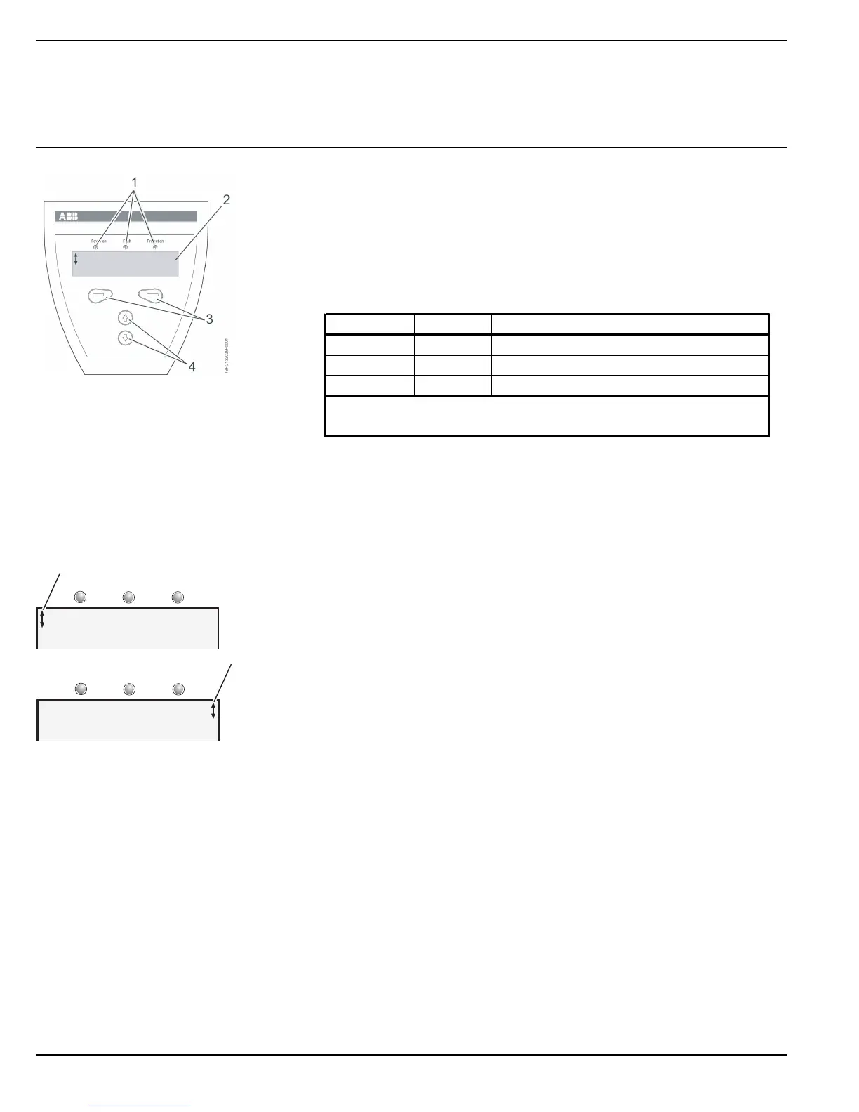
6:1.2 Design
The HMI consists of:
• Status indication LED indicators
• LCD display
• Selection and Navigation keys
The LED indicators work as follows:
The keypad is based on the same user concept as today’s mobile phones.
The LCD contains two rows with 20 characters each.
The top row presents various information depending on its state. The
bottom row indicates which function is currently selected.
A scrolling icon indicates what parameter or setting value is possible to
change at the position.
The
Selection keys
normally have more than one function, such as
selecting, changing and storing parameters. See the text on the bottom
row of the LCD.
The
Navigation keys
are used for navigating through the various menus
to the desired setting.
When selecting from a list, the scrolling is done in a closed loop fashion.
LED Color Description
Power on Green Control voltage connected.
Fault Red Indicates faults.
Protection Yellow Indicates protective function has activated.
When a Fault or Protection LED is activated, the LCD displays the
actual fault or protection.
U= 0% I=0.0A
Menu
Figure 1: Human-Machine
Interface
1 Status indication LEDs
2 LCD display
3 Selection keys
4 Navigation keys
Figure 2: Menu examples
1 Scrolling icons
Power on ProtectionFault
Power on ProtectionFault
1
1
Setting Ie 100A
Change Back
Setting Ie 100A
Store Cancel
 Loading...