Publication 2711-UM014B-EN-P
13-4 Troubleshooting and Maintenance
Indicators
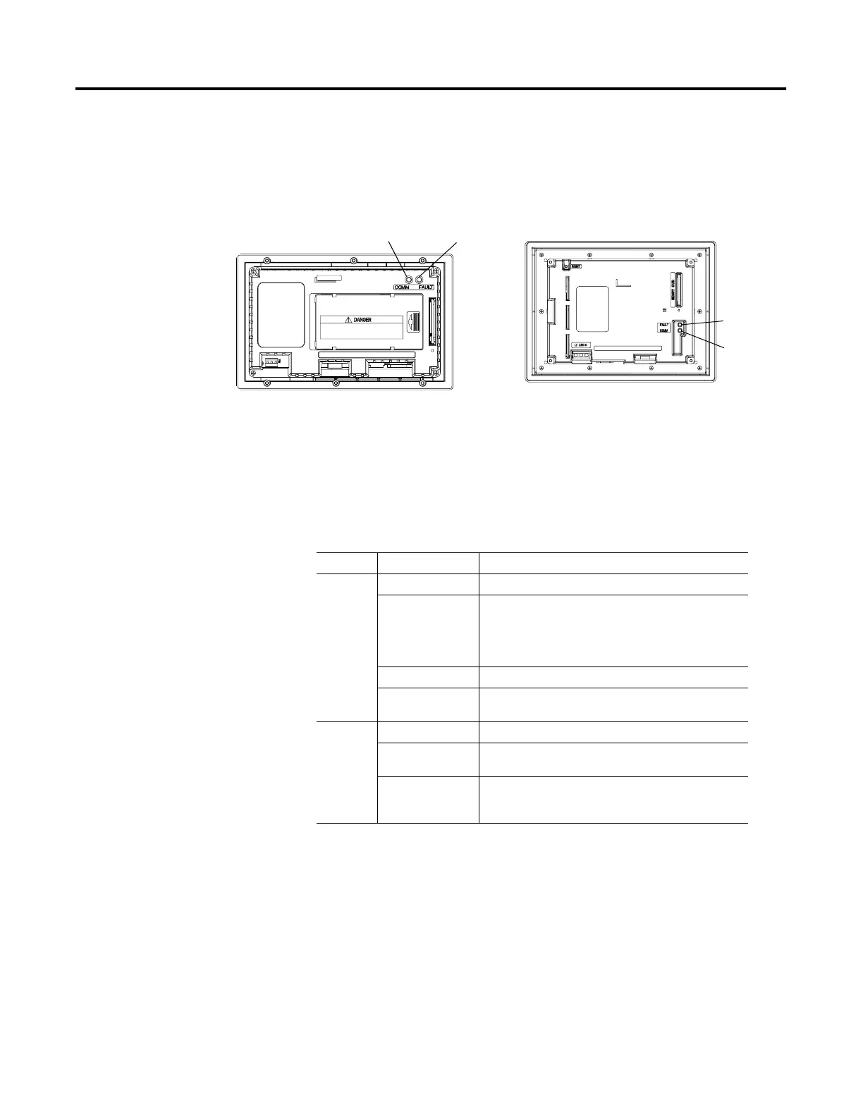
On PanelView terminals (except PanelView 300 Micro), use the
COMM and Fault LED indicators to isolate operating problems. The
illustration below shows the location of these indicators on some
terminals. See chapter 1 for LED locations on other terminals.
On PanelView 300 Micro terminals, view the Comm and Fault
indicators in the terminal configuration mode (Communication Setup
selected).
DF1, DH-485, DH+ LED Indications
1 Comm LED stays on until powerup self-tests are complete.
PV550 Back View
PV900 Back View
PV600/PV1000 is similar
COMM LED
Fault LED
Fault LED
COMM LED
LED This Pattern: Indicates:
Comm
1
Solid Fill Normal operating state (no communication faults).
No Fill Fault detected.
• Make sure controller is run mode
• Verify baud settings of terminal and controller
• Verify proper terminal to controller
connections
Flashing When power is first applied (momentarily).
Blinking No communications established. For DF1 terminals, the
Comm indicator flashes until an application is loaded.
Fault No Fill Normal operating state
Solid Fault detected. Cycle power to the terminal. If the fault
still exists, the terminal requires servicing.
Blinking Hardware is functioning but no application is loaded or
the current application is corrupt. Reload the
application into the terminal.
 Loading...