
Do you have a question about the Allen-Bradley PV300 Micro and is the answer not in the manual?
| Brand | Allen-Bradley |
|---|---|
| Model | PV300 Micro |
| Category | Touch terminals |
| Language | English |
Outlines preface content: manual overview, audience, conventions, related publications, and support.
Provides a structured overview of the manual's chapters and their respective purposes.
Describes the target audience and required technical knowledge for understanding the manual.
Explains the specific formatting and terminology conventions used throughout the document.
Refers readers to the glossary for definitions of any unfamiliar terms used in the manual.
Advises following provided instructions for installing PanelView terminals in panels or enclosures.
Directs readers to Appendix C for details on compliance with European Union Directives.
Lists additional publications and online resources for PanelBuilder32 software and controller information.
Provides contact information and resources for technical assistance, including FAQs and software upgrades.
Highlights new features, specifically Ethernet communications support for various PanelView terminals.
Lists topics covered in the chapter: intended uses, types, applications, configuration, and accessories.
Describes the general applications of PanelView terminals in machine control and monitoring tasks.
Lists options like display size, input method, and communication ports available for PanelView terminals.
Details the PanelView 300 terminal's 24V DC power and available communication ports.
Describes the PV300 Micro's 24V DC power, lack of printer port, and single RS-232 port.
Covers PV550 touch screen terminals with 24V DC power and various communication ports.
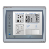
Details PV600 color terminals, their power options, and available communication ports.
Describes PV900 monochrome terminals, noting they are no longer available for purchase.
Lists PV900 color terminals with their communication ports and catalog numbers.
Details PV1000 color terminals, their power options, and communication port configurations.
Covers PV1000 grayscale terminals, their power options, and communication port configurations.
Describes PanelView 1400 color terminals, their communication ports, and catalog numbers.
Details the front features of the PanelView 300 Micro keypad terminal, including function and cursor keys.
Explains the back features of the PV300 Micro, including ports, LEDs, and the sealing gasket.
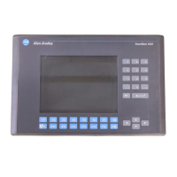
Describes the front features of the PanelView 300 keypad terminal, including function, cursor, and entry keys.
Details the back features of the PanelView 300, including ports, LEDs, and memory card slot.
Shows the front features of PanelView 550 keypad, keypad & touch, and touch screen terminals.
Illustrates the back view and identifies ports for PV550 keypad/keypad & touch terminals.
Details the back view and identifies ports for PanelView 550 touch screen terminals.
Shows the front features of PanelView 600 keypad, keypad & touch, and touch screen terminals.
Identifies ports and features on the back of PV600 keypad/keypad & touch terminals.
Details the back view and ports for PanelView 600 touch-screen terminals.
Shows the front features of PanelView 900/1000 keypad and touch screen terminals.
Identifies back features and ports for PanelView 900/1000 terminals.
Details the front features of PanelView 1400 keypad and touch screen terminals.
Illustrates and identifies back and side features/ports for PanelView 1400 terminals.
Explains how PanelView terminals operate with custom applications and the Configuration Mode menu.
Describes how touch screen terminals are operated by interacting with screen objects.
Explains how keypad terminals are operated using function keys corresponding to screen objects.
Details functions configurable from the menu, such as language, communications, and printer setup.
Explains the types of terminal messages displayed, including status, faults, and prompts.
Describes the printing capabilities of terminals equipped with an RS-232 printer port.
Explains the Alarm List queue for storing triggered alarms and the data it contains.
Lists available accessories like software, legend kits, memory cards, and retainers.
Describes self-adhesive filters that minimize display reflections for improved visibility.
Lists catalog numbers and descriptions for DH-485 operating and programming cables.
Lists available power supplies and link couplers for PanelView terminals and networks.
Details the utility for transferring PVA files between terminals and computers.
Lists various RS-232 cables for connecting PanelView terminals to computers or printers.
Lists cables for Remote I/O and DH+ connections, specifying types and lengths.
Lists replacement parts like backlight lamps, clock modules, and mounting clips for PanelView terminals.
Lists specific backlight lamps for various PanelView models, including catalog numbers.
Lists real-time clock modules for different PanelView models and their battery life.
Lists panel mount clips and studs required for terminal installation into panels.
Lists the terminal block connector used for Remote I/O ports on PanelView terminals.
Lists power input connectors, specifically for the PanelView 300 Micro terminal.
Outlines topics: wiring, safety, power connection, resetting, and power-up sequences for PanelView terminals.
Provides crucial guidelines for wiring PanelView terminals, referencing NFPA 70E and NEC articles.
Details AC electrical ratings for PanelView terminals and steps for AC power connection.
Lists electrical ratings for DC PanelView terminals and provides DC power connection guidance.
Explains procedures to reset PanelView terminals using key combinations or reset buttons.
Describes the terminal's self-tests during power-up and the initial display screens shown.
Outlines chapter topics: config mode, language, memory cards, communications, presets, and screen settings.
Explains parameter setting via terminal or PanelBuilder32, noting application priority over terminal settings.
Details how to access the Configuration Mode menu on keypad and touch screen terminals.
Explains how to select the terminal's display language from a list of supported options.
Describes transferring applications and files to/from memory cards via the Configuration Mode menu.
Explains setting communication parameters for various protocols through the Configuration Mode menu.
Details configuring DH-485 settings like Max Node, Node Address, and Baud Rate.
Explains configuring DH+ settings such as Node address and Baud rate.
Describes displaying and configuring Remote I/O settings, noting most are read-only.
Details configuring ControlNet settings like Node Address and Interscan Delay.
Explains configuring DeviceNet settings like Node Address, Baud Rate, and Input/Output Size.
Describes configuring DF1 parameters including Parity, Baud Rate, and Error Detection.
Explains configuring EtherNet/IP settings like DHCP/BootP, IP Address, and Interscan Delay.
Describes setting control object values for power-up, including repeat rate and delay.
Explains accessing terminal information like boot, firmware, hardware, filename, and font file details.
Details adjusting screen settings such as contrast, video mode, and screen saver.
Explains screen settings for PV300, including contrast, video mode, reset video, and screen saver.
Details screen settings for PV550, including backlight, contrast, video mode, and backlight timeout.
Explains screen setup for PV600/900/1000 color models, including intensity, screen saver, and video mode.
Details screen setup for PV900 monochrome models, including intensity, video mode, and screen conditioner.
Explains screen setup for PV1000 grayscale models, including video mode, screen saver, and screen intensity.
Details screen setup for PV1400 color models, including screen saver, degauss, and intensity.
Explains how to reset the date and time on PanelView terminals using screen buttons or function keys.
Details how to configure printer parameters like handshaking, baud rate, and communication parameters.
Lists topics: supported cards, retainer, loading/storing applications, and removing cards.
Lists compatible memory cards and ATA cards supported by PanelView terminals and computers.
Explains the purpose and required installations for the memory card retainer for safety.
Provides step-by-step instructions to load an application from a memory card into the PanelView terminal.
Details the procedure to save an application from the terminal onto a memory card.
Explains how memory cards store font files for languages and the need for the card to remain inserted.
Provides the procedure for safely removing a memory card from the PanelView terminal.
Lists common operating procedures: screen security, push buttons, control lists, numeric entry, ASCII entry, screen selectors, indicators, etc.
Emphasizes the application designer's responsibility for documenting and understanding application operation.
Highlights special considerations for PV300 Micro cursor key assignments and their impact on operations.
Explains how some screens can be restricted with passwords, managed by the application designer.
Describes how push buttons function like mechanical ones and their various appearances and behaviors.
Explains how control lists modify bits or values, similar to push buttons, and how to activate them.
Describes cursor movement within control lists, including wrap-around and top/bottom movement.
Details screen-based list keys for navigating control lists on touch screen terminals.
Explains how controller-operated or inactive items in piloted control lists affect cursor display.
Describes numeric entry cursor points and data entry via scratchpads.
Explains keypad enable buttons that open a numeric entry scratchpad upon selection.
Details the thumbwheel scratchpad for value entry on terminals without keypads or touch screens.
Explains how ASCII entry controls send alphanumeric strings and use scratchpads for input.
Describes the ASCII scratchpad for touch screen terminals, including character selection and modes.
Details the thumbwheel scratchpad for ASCII entry on PV300 Micro/300 terminals.
Describes the ASCII scratchpad for touch screen terminals, including character selection and modes.
Explains the ASCII scratchpad for PV900/1000/1400 touch screen terminals, including shift and caps modes.
Mentions ASCII scratchpad availability in multiple languages with SHF control toggling.
Describes screen list selectors and screen buttons used to navigate application screens.
Explains cursor movement within screen lists, similar to control lists.
Details screen-based list keys for navigating screen lists on touch terminals.
Explains how list indicators highlight items based on controller status, with automatic scrolling.
Describes multistate indicators that display status via text, fill, or graphics, supporting up to 2,000 states.
Explains bar graphs as graphical representations of variable values with various scales and fill patterns.
Describes analog gauges that use a rotating needle to display process variables on a circular scale.
Details numeric data displays showing values with properties like zero fill, fixed/floating points, and scaling.
Explains message displays showing alphanumeric text, variable data, or graphics when triggered by a controller.
Describes how time and date information is displayed, including various formats for date and time.
Details the printing capabilities of terminals with RS-232 ports, including what can be printed.
Explains alarm handling features like Alarm Banners, Alarm buttons, and the Alarm List.
Lists topics: hazardous locations, enclosures, tools, dimensions, clearances, cutout, and panel installation.
Advises on suitability for Class 1, Division 2 locations and provides explosion hazard warnings.
Discusses panel/enclosure requirements, NEMA ratings, ventilation, and ambient temperature for PV300 Micro.
Lists tools needed for installation, such as socket wrenches and torque wrenches.
Provides physical dimensions for mounting the PV300 Micro terminal.
Shows recommended panel cutout dimensions for the PV300 Micro terminal.
Specifies required side, top, bottom, and back clearances for ventilation and maintenance.
Provides step-by-step instructions for mounting the PV300 Micro terminal into a panel cutout.
Lists topics: hazardous locations, enclosures, tools, dimensions, clearances, cutout, and panel installation.
Refers to nameplate for certifications and warns about operating temperature codes and ignition temperatures.
Discusses panel/enclosure requirements, NEMA ratings, ventilation, and ambient temperature for PV300 terminal.
Lists tools needed for panel cutout and installation, such as socket wrenches.
Provides physical dimensions for mounting the PV300 keypad terminals.
Shows recommended panel cutout dimensions for the PV300 terminal.
Specifies required side, top, bottom, and back clearances for PV300 mounting, air flow, and maintenance.
Provides step-by-step instructions for mounting the PV300 terminal into a panel cutout.
Lists topics: hazardous locations, enclosures, tools, dimensions, clearances, cutout, and panel installation.
Refers to nameplate for certifications and warns about operating temperature codes and ignition temperatures.
Discusses panel/enclosure requirements, NEMA ratings, ventilation, and ambient temperature for PV550 terminal.
Lists tools needed for panel cutout and installation, such as socket wrenches.
Provides physical dimensions for PV550 keypad/touch screen and touch screen terminals.
Specifies clearances for PV550 mounting, air flow, maintenance, memory card access, and wiring connections.
Shows recommended panel cutout dimensions for PV550 keypad/touch screen and touch screen terminals.
Provides step-by-step instructions for mounting PV550 terminals into a panel cutout.
Lists topics: hazardous locations, enclosures, tools, dimensions, clearances, cutout, and panel installation.
Refers to nameplate for certifications and warns about operating temperature codes and ignition temperatures.
Discusses panel/enclosure requirements, NEMA ratings, ventilation, and ambient temperature for PV600 terminal.
Lists tools needed for panel cutout and installation, including screwdrivers and torque wrenches.
Provides physical dimensions for PV600 keypad/touch screen and touch screen terminals.
Shows recommended panel cutout dimensions for PV600 keypad/touch screen and touch screen terminals.
Specifies clearances for PV600 mounting, air flow, maintenance, memory card access, and wiring connections.
Provides step-by-step instructions for mounting PV600 terminals into a panel cutout.
Lists topics: hazardous locations, enclosures, tools, dimensions, clearances, cutout, and panel installation.
Refers to nameplate for certifications and warns about operating temperature codes and ignition temperatures.
Discusses panel/enclosure requirements, NEMA ratings, ventilation, and ambient temperature for PV900/1000 terminals.
Lists tools needed for panel cutout and installation, including screwdrivers and torque wrenches.
Provides physical dimensions for PV900 touch and keypad terminals.
Shows mounting dimensions for PV1000 grayscale and color terminals.
Specifies clearances for PV900/1000 mounting, air flow, maintenance, memory card access, and legend strip installation.
Shows recommended panel cutout dimensions for PV900 and PV1000 terminals.
Provides step-by-step instructions for mounting PV900/1000 terminals into a panel cutout.
Lists topics: enclosures, tools, dimensions, clearances, cutout, and panel installation.
Discusses panel/enclosure requirements, NEMA ratings, ventilation, and ambient temperature for PV1400 terminal.
Lists tools needed for panel cutout and installation, including socket drivers and extension rods.
Provides physical dimensions for PV1400 touch and keypad terminals.
Specifies clearances for PV1400 mounting, air flow, maintenance, and memory card access.
Shows recommended panel cutout dimensions for PV1400 keypad and touch screen terminals.
Provides instructions for mounting PV1400 terminals using clips.
Provides instructions for mounting PV1400 terminals using mounting studs.
Lists topics: network/device connections, cable charts, Remote I/O, DH+, DH-485, RS-232, ControlNet, DeviceNet, EtherNet/IP, PV300 Micro, computer/printer connections.
Provides guidelines for wiring PanelView terminals, referencing NFPA 70E and NEC articles for safety.
Summarizes PanelView terminal connections to controllers and network interface modules in tables.
Lists cables for transferring application files between PanelView terminals and personal computers.
Describes connections for Remote I/O PanelView terminals, including ports and supported controllers.
Lists controllers and scanners compatible with PanelView terminals for Remote I/O connections.
Details how to connect a PanelView terminal to a Remote I/O scanner using specific cables and guidelines.
Explains how to transfer applications via DH+ link to PLC-5/SLC controllers using Remote I/O Pass-Through.
Describes connections for DH+ PanelView terminals, including ports and system configuration.
Illustrates typical DH+ system setups with SLC, PLC, and PanelView terminals.
Details how to connect PanelView terminals to a DH+ link using specific cables and guidelines.
Describes connections for DH-485 PanelView terminals, including ports and controller connections.
Details point-to-point connections for DH-485 terminals to SLC controllers using specific cables.
Shows how to connect DH-485 terminals to multiple SLC controllers on a network via AIC Link Coupler.
Explains connecting RS-232 (DH-485) terminals to MicroLogix controllers via AIC+ Link Coupler.
Details connecting a computer to RS-232 (DH-485) terminals for application transfers.
Instructs on connecting the Earth Ground terminal for specific PV models using the 1747-PIC converter.
Explains how to connect a Hand-Held Terminal (HHT) to PanelView terminals using a specific cable.
Describes RS-232 (DF1) connections, compatible controllers, and terminal ports.
Lists controllers compatible with RS-232 (DF1) terminals for full duplex communication.
Details point-to-point connections for RS-232 (DF1) terminals to SLC, CompactLogix, and MicroLogix controllers.
Illustrates connecting DF1 terminals to controllers via DeviceNet or EtherNet/IP networks.
Describes connections for ControlNet PanelView terminals, including protocol and compatible controllers.
Lists controllers compatible with ControlNet PanelView terminals for messaging.
Details ControlNet communication ports and RS-232 serial ports on PanelView terminals.
Illustrates a typical ControlNet network setup with PanelView terminals and controllers.
Provides pinout information for connecting PanelView terminals to a ControlNet network.
Lists ControlNet cables, taps, and connectors, referring to planning manuals.
Describes DeviceNet PanelView terminals, including connectors and typical network configurations.
Lists cables for connecting PanelView terminals to a DeviceNet network and describes terminal block pinouts.
Illustrates a typical DeviceNet network with PanelView terminals, PLC-5, and SLC controllers.
Explains how PanelView terminals communicate on EtherNet/IP networks with various devices and controller access.
Details the RJ45 Ethernet connector pinout and provides guidance on straight-through vs. cross-over cables.
Illustrates a typical EtherNet/IP network with PanelView terminals, controllers, and IP addresses.
Details connecting the PV300 Micro terminal, including RS-232 port and MicroLogix controller connections.
Explains direct connections for PV300 Micro to various controllers using specified cables and protocols.
Describes operating PV300 Micro DH-485 versions via an AIC+ module.
Explains operating PV300 Micro on DeviceNet using DF1 protocol via a DNI module.
Details transferring applications between a computer and PV300 Micro using specified cables and software.
Shows connections for downloading applications or connecting printers via RS-232 serial port.
Lists topics: isolating problems, routine maintenance, troubleshooting chart, LED indicators, cleaning, and replacing parts.
States that only a voltmeter is needed for troubleshooting, no electronic diagnostic equipment required.
Introduces the chart listing common problems, causes, and corrective actions for terminal issues.
A detailed chart listing problems, probable causes, and corrective actions for terminal issues.
Explains the function of COMM and Fault LEDs on PanelView terminals for isolating operating problems.
Provides instructions and warnings for safely cleaning the display window using mild soap or alcohol.
Explains the real-time clock module, its battery, lifespan, and non-replaceability on PV300 Micro.
Mentions that replacement backlights are available and notes non-replaceability for certain models.
Lists electrical, mechanical, display, terminal memory, and environment specifications for the PV300 Micro.
Lists electrical, mechanical, display, and terminal memory specifications for the PanelView 300.
Lists electrical, mechanical, display, and terminal memory specifications for PanelView 550 terminals.
Lists electrical, mechanical, display, and terminal memory specifications for PV600 color terminals.
Lists electrical, mechanical, display, and terminal memory specifications for PV600 color touch-only terminals.
Lists electrical, mechanical, display, and terminal memory specs for PV900 monochrome and color terminals.
Lists electrical, mechanical, display, and terminal memory specifications for PV1000 color and grayscale terminals.
Lists electrical, mechanical, display, and terminal memory specifications for the PanelView 1400 color terminal.
Lists baud rates and distance maximums for DH-485, DH+, RS-232, Remote I/O, DeviceNet, ControlNet, EtherNet/IP, and DF1.
Categorizes terminal messages into Status, Reminder, Warning, and Fault messages for clarity.
Lists error numbers, messages, types, meanings, and recommended actions for general terminal issues.
Lists specific error numbers, messages, meanings, and recommended actions for DH-485 communication issues.
Lists error numbers, messages, meanings, and recommended actions for DF1 communication problems.
Lists error numbers, types, meanings, and recommended actions for ControlNet communication issues.
Lists error numbers, types, meanings, and recommended actions for Remote I/O communication issues.
Lists error numbers, types, meanings, and recommended actions for DH+ communication issues.
Explains DeviceNet communication status codes and their recommended actions for troubleshooting.
Lists DeviceNet fault codes, their meanings, and recommended actions for resolution.
Lists general terminal alert codes, alert types, meanings, and recommended actions for diagnostics.
Lists ControlNet error codes appearing on the application or configuration screen, with recommended actions.
Lists EtherNet/IP error codes appearing on the terminal screen, with meanings and recommended actions.
Explains messages displayed during Remote I/O communication failures and object state handling.
Lists self-test numbers that appear during powerup and their indications for diagnostics.
Details the apparatus testing against Council Directives for EMC and Low Voltage, and relevant standards.
Defines the product's intended use according to EMC standards for industrial environments.
Provides recommendations for wiring to reduce noise, protect the circuit, and route cables.
States that Declarations of Conformity are available on the ab.com website under Product Certification.
Defines adapter as a ControlNet device responding to scanner messages, also called a slave device.
Defines address as a character string identifying a memory location or physical I/O circuit.
Defines application in PanelBuilder32 context as screens replacing control panel functions.
Defines application file as containing configuration info for a PanelView terminal, in .PVA or .PBA format.
Defines ATA card as a drive controller and memory storage device, accessible like a hard drive.
Defines baud as a unit of signaling speed based on discrete conditions or signal events per second.
Defines boot revision as the revision number of the terminal's boot code.
Defines bridge as a device allowing network data transfer between links.
Defines controller as a unit (PLC, relay panel) controlling machine or process elements.
Defines cursor keys as arrow keys on the keypad used for navigation and selection.
Defines DF1 as an Allen-Bradley communication protocol based on ANSI X3.28-1976 specification.
Refers to "upload/download" for definition.
Defines DH-485 link as an Allen-Bradley token-passing carrier-band link.
Defines DH+ link as an Allen-Bradley token-passing baseband link.
Defines DHCP as software for dynamic IP address allocation on TCP/IP networks.
Defines Domain Name as a character string mapping a local domain to a DNS server's IP address.
Defines DNS Server as converting host names to IP addresses.
Defines EMI as Electromagnetic Interference affecting electronic equipment performance.
Defines EPROM as erasable programmable read-only memory, nonvolatile.
Defines EEPROM as electrically erasable PROM used for PanelView applications.
Defines firmware as logic stored in read-only memory.
Defines function keys (F1-F10, F1-F16, F1-21) used to initiate functions, often user-defined.
Defines gateway address as a 32-bit address connecting IP networks, used for inter-network data transfer.
Defines interscan delay as the time PanelView waits before re-reading controller data.
Defines IP address as a unique 32-bit address for a node on an EtherNet/IP network.
Defines keeper as the network controller of a ControlNet network.
Defines keypad as a set of keys used for data entry on terminals.
Defines LED as Light-Emitting Diode.
Defines Memory Card as storage for PanelView applications and font files.
Defines MicroLogix as an Allen-Bradley programmable controller.
Defines NEMA standards for electrical equipment approved by the National Electrical Manufacturers Association.
Defines network as a collection of connected nodes, paths, repeaters, and bridges.
Defines NAP as a port for temporary access to a ControlNet network via RJ-45.
Defines NUT as the ControlNet network update time for communications link.
Defines node as a connection point providing medium access.
Defines PanelBuilder32 software as a Windows program for developing PanelView applications.
Defines PanelView terminal as an interface providing operator interaction with logic controllers.
Defines PC as Personal Computer, Programmable Controller, or Printed Circuit.
Defines PCCC as Programmable Controller Communication Commands.
Defines PGM setting for baud rate via explicit message request, retained by daughtercard.
Defines PLC controller as an Allen-Bradley programmable controller with PLC prefix.
Defines preset value as a value loaded into a controller data table when an application starts.
Defines programmable controller as a solid-state control system for implementing specific functions.
Defines real time clock as providing internal time, day, month, and year.
Defines remote I/O as I/O connected to a processor across a serial link.
Defines remote I/O link as a serial link for carrying I/O data between processors and adapters.
Defines repeater as a two-port component transmitting data between segments.
Defines restore as loading an application from a memory card.
Defines RS-232 as an EIA standard for serial binary communication.
Defines RS-485 as an EIA standard for balanced-voltage digital interface circuits.
Defines scheduled messages as occurring at regular intervals, assigned to NUT portions.
Defines SELV as a voltage not exceeding 42.4V peak/dc, isolated from main power.
Defines scratchpad as a window for data entry using the terminal or screen keypad.
Defines screen as the viewing surface or visual image on a screen.
Defines segment as trunk-cable sections connected via taps with terminators.
Defines SLC as an Allen-Bradley programmable controller with SLC prefix.
Defines SMAX as the highest ControlNet node address for scheduled communication.
Defines subnet mask as a 32-value parameter for IP addresses in divided networks.
Defines tap as a hardware component connecting devices to a ControlNet trunk cable.
Defines touch cell as a rectangular area on the display that senses touch.
Defines touch screen as the display window responding to touch.
Defines trunk cable as the bus or central part of a cable system.
Defines unscheduled messages as sent on an as-needed basis during the unscheduled network update interval.
Defines UMAX as the highest ControlNet node address for unscheduled communication.
Defines upload/download as reading/writing large data blocks between devices, depending on read/write and initiator.
Details the apparatus testing against Council Directives for EMC and Low Voltage, and relevant standards.
Defines the product's intended use according to EMC standards for industrial environments.
Provides recommendations for wiring to reduce noise, protect the circuit, and route cables.
States that Declarations of Conformity are available on the ab.com website under Product Certification.