Machine description
4812160001_A.pdf2014-08-25
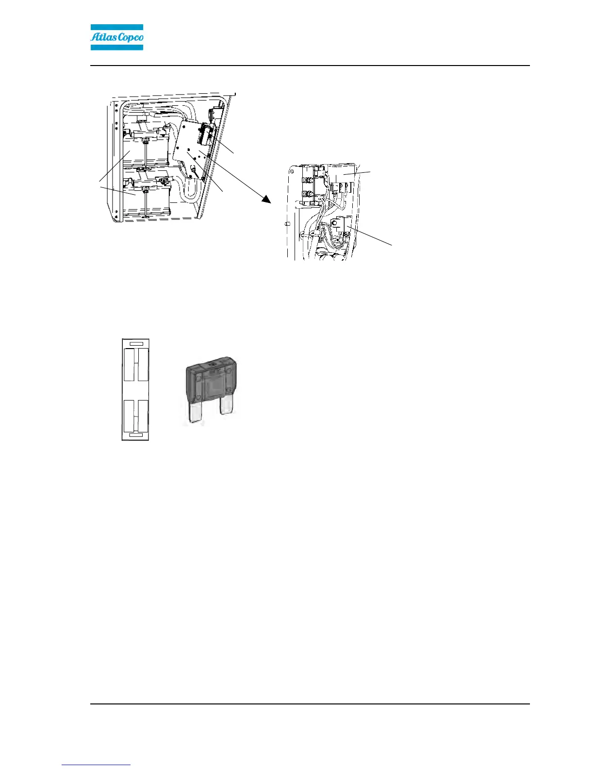
Fuses at master switch (Cummins)
Fig. Cover, left side
1. Fuse box
2. Batteries (x2)
3. Battery disconnector plate
1
3
2
The fuse box (1) is located inside the cover by the
steps on the left-hand side of the roller.
This is also where the batteries (2) are, and the starter
relay (4) and preheating relay (5) are placed behind
the battery disconnector plate (3).
5
4
4. Starter relay, 50A
5. Preheating relay, 120A
Fuse box at master switch (Cummins)
Fig. Fuse box, battery disconnector
switch
1
3
2
4
The figure shows the position of the fuses.
The amperage and function of the fuses are shown
below. All fuses are flat pin fuses.
1. Main fuse 50A1. Main fuse 50A
2. Cab 30A2. Cab 30A
3. Diesel engine ECU 30A3. Diesel engine ECU 30A
4. Grid heater 40A4. Grid heater 40A
53
 Loading...