Version 5.8 13 July 2009
Installation Manual 2. Physical Description
2 Physical Description
This section provides a physical description of the device.
2.1 Components
The device includes the following components:
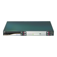
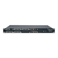
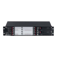
A 19-inch, 2U high rack-mount chassis (refer to ''Chassis'' on page 16).
Hot-swapp
able communication blades:
• Alarm, Status and Synchronization blade (SA/M3K): perform various functions
such as clock synchronization (refer to ''Alarm, Status and Synchronization Blade''
on page 33)
• 6310 blad
es: regarded as a complete gateway/media server module, supporting
all necessary functions for voice, data, and fax streaming over IP networks (refer
to ''6310 Blade'' on page 22). The bla
de is supplied with a rear input/output (I/O)
module referred to as the Rear Transition Module (RTM). RTM-6310 provides the
I/O connections to the supported interfaces (Gigabit Ethernet, and T3 PSTN or
STM-1/OC-3, depending on system).
• 8410 blades: regarded as a complete gateway module, supporting all necessary
functions for voice, data, and fax streaming over IP networks (refer to ''8410
Blade'' on page 28). Th
e blade is supplied with RTM(s). RTM-8410 provides the
I/O connections to the supported interfaces (Gigabit Ethernet and DS1 PSTN).
The number and type of blades housed in the device's chassis depends on the device
(Mediant 3000 or IPmedia 3000) and mode (Simplex or High Availability - HA), as
shown in the table below:
Table 2-1: Number and Type of Blades per Device
Device Mode Number of cPCI Blades
SA/M3K Implementing 6310 Series Implementing 8410 Series
6310
Blade
RTM-
6310
RTM-6310
Redundant
8410
Blade
RTM-8410
Mediant
3000
Simplex 1 1 1 - 1
1: 16 Spans
2: 42-84
Spans
HA 2 2 1 1 2
2: 16 Spans
2: 42-84
Spans
IPmedia
3000
Simplex 1 1 1 - N/A N/A
System alarm LEDs and ACO button (refer to ''Alarm LEDs and ACO Button'' on page
21)
Cooli
ng system (refer to ''Chassis Cooling System'' on page 35):
• One Fa
n Tray module (FM/M3K)
• An Air Filter (AF/3K) located within the Fan Tray module
 Loading...