Version 5.8 15 July 2009
Installation Manual 2. Physical Description
Table 2-2: Front-Panel Component Descriptions
Item # Component Description
1
Electrostatic discharge (ESD) terminal.
2
Fan Tray module (housing the Air Filter), providing system alarm LEDs, ACO button, and
component location diagram indicating numbering of blade slots and Power Supply units.
3
Latches and screws for securing blades to chassis.
4
Power Supply units.
5
Power Supply LEDs.
6
Integral mounting brackets for mounting the chassis in a standard 19-inch Telco rack.
7
Blade slots (currently covered with blank panels) for housing the blades.
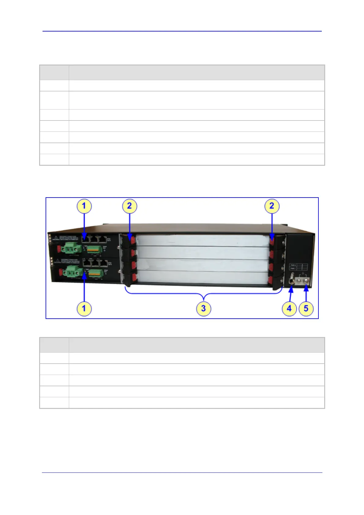
The main components of the device's rear panel (without RTMs) are shown below:
Figure 2-2: Rear Panel Main Components
Table 2-3: Rear-Panel Component Descriptions
Item # Component Description
1
Two Power Entry Modules (PEM).
2
Latches and screws to secure blades and modules to chassis.
3
Slots (currently covered with blank panels) for housing the RTMs.
4
ESD terminal lug.
5
Earthing terminal (one-hole G-32 lug and 6-8 AWG wire).
 Loading...