Installation Manual 62 Document #: LTRT-94704
Mediant 3000 & IPmedia 3000
Table 3-7: Alarm Terminal Block Pin Details
Pin Pin Description
1 - Common 2 – Normally Open (N.O) “CRT” (Critical Alarm)
3 - Common 4 – N.O. “MJR” (Major Alarm)
5 - Common 6 – N.O. “MNR” (Minor Alarm)
7 – Alarm In 8 – GND “IN” (User Alarm In)
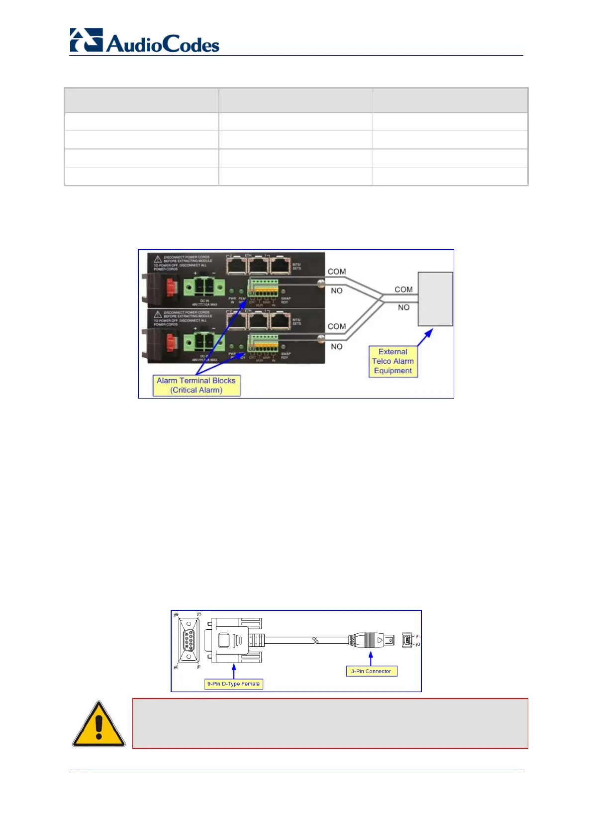
It is recommended to provide a dual-redundant solution by wiring the two PEMs' alarm
terminal blocks to the alarm device, as shown in the figure below:
Figure 3-16: Normal Logic Alarm Connection (Redundancy Scheme)
3.3.6 Connecting the RS-232 Port to a PC
For RS-232 interface, a crossover RS-232 cable adapter (of approximately two meters) is
supplied. This cable adapter provides a 3-pin connector for connecting to the 6310/8410
blade's RS-232 port (located on the front panel) and a DB-9 connector (on the other end of
the cable) for the COM1 or COM2 RS-232 communication port on your PC.
¾ To connect the device's RS-232 port to your PC:
1. Plug the RS-232 cable adapter's 3-pin connector into the RS-232 port (labeled 1010),
located on the blade's front panel.
2. Connect the DB-9 female connector (on the other end of the RS-232 cable adapter) to
your PC's COM1 or COM2 port.
Figure 3-17: RS-232 Cable Adapter (Supplied)
Note: The RS-232 port is not intended for permanent connection.
 Loading...