Version 5.8 65 July 2009
Installation Manual 3. Installation
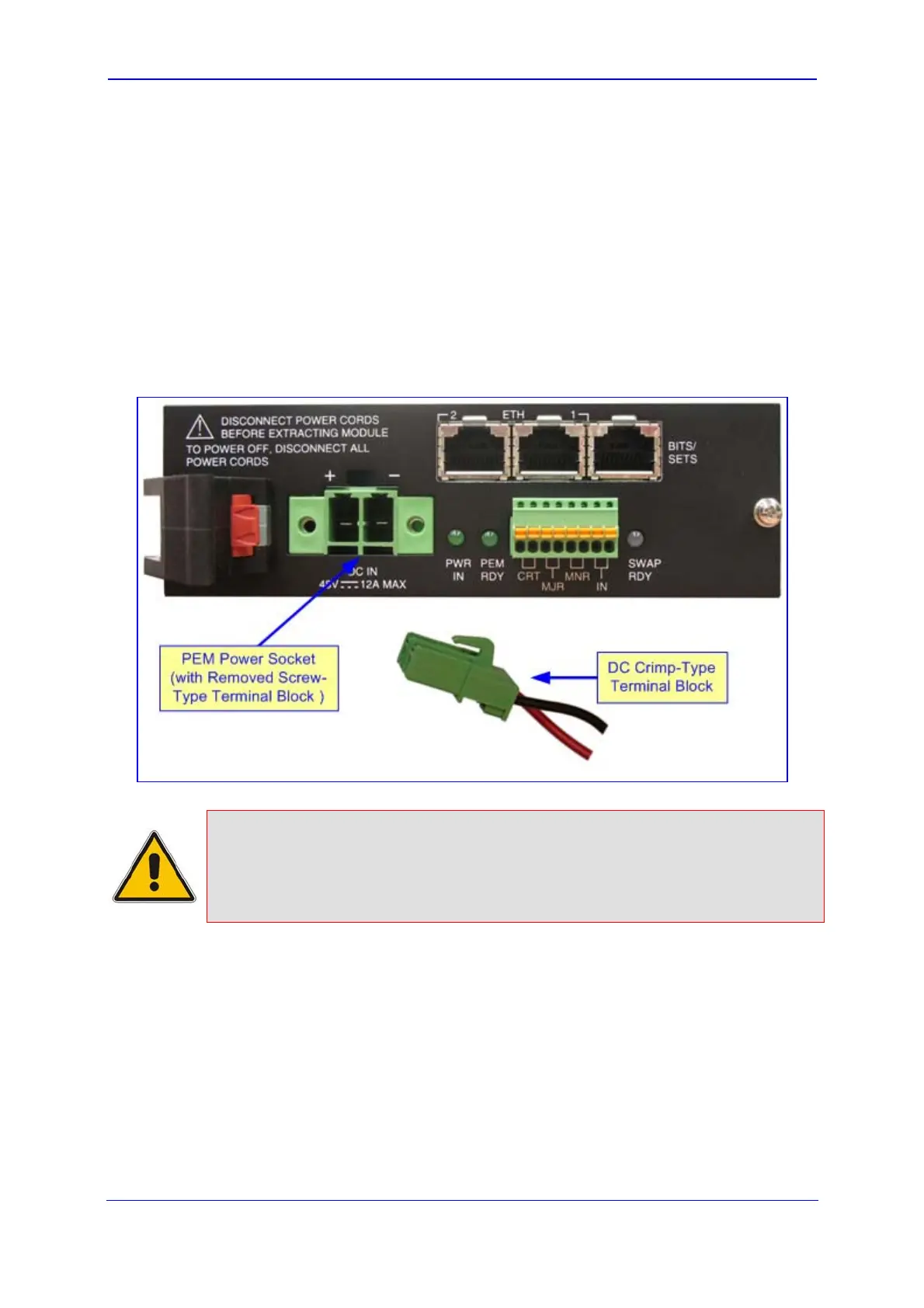
¾ To connect power using a DC terminal block crimp connector:
1. Remove the terminal block screw from the chassis power socket (labeled DC IN), by
unscrewing the two screws located on the front of the terminal block.
2. Connect the two insulated wires to the correct DC power outlet. Ensure that the
connections to the DC power outlet maintain the correct polarity (positive / negative).
3. Insert the supplied DC power feed cable crimped to the terminal block into the DC inlet
(labeled DC IN). Ensure that the hook on the terminal block snaps into the groove
above the DC inlet.
When power is received, the PWR IN LED is lit (green).
Figure 3-19: Power Feed Cable Terminated with Crimp-Connection Type DC Terminal Block
Notes:
• To ensure power redundancy, both PEM modules must be connected to
the power source.
• To power down the device, disconnect both DC power sources.
 Loading...