Version 5.8 21 July 2009
Installation Manual 2. Physical Description
3. Slot 3 front panel: Standby (redundant) 8410 blade (applicable only to Mediant
3000 HA). In Simplex mode, this slot is covered with a blank panel.
4. Slot 4 front panel: Standby (redundant) Alarm and Status blade (applicable only
to Mediant 3000 HA). In Simplex mode, this slot is covered with a blank panel.
5. Blank panels covering unoccupied slots.
6. Slot 2 rear panel: RTM-8410 providing PSTN E1/T1 (Trunks 1 to 42, or 1 to 16)
and dual Gigabit Ethernet interfaces.
7. Slot 4 rear panel: RTM-8410 providing PSTN E1/T1 (Trunks 43 to 84) interfaces
and Gigabit Ethernet interfaces.
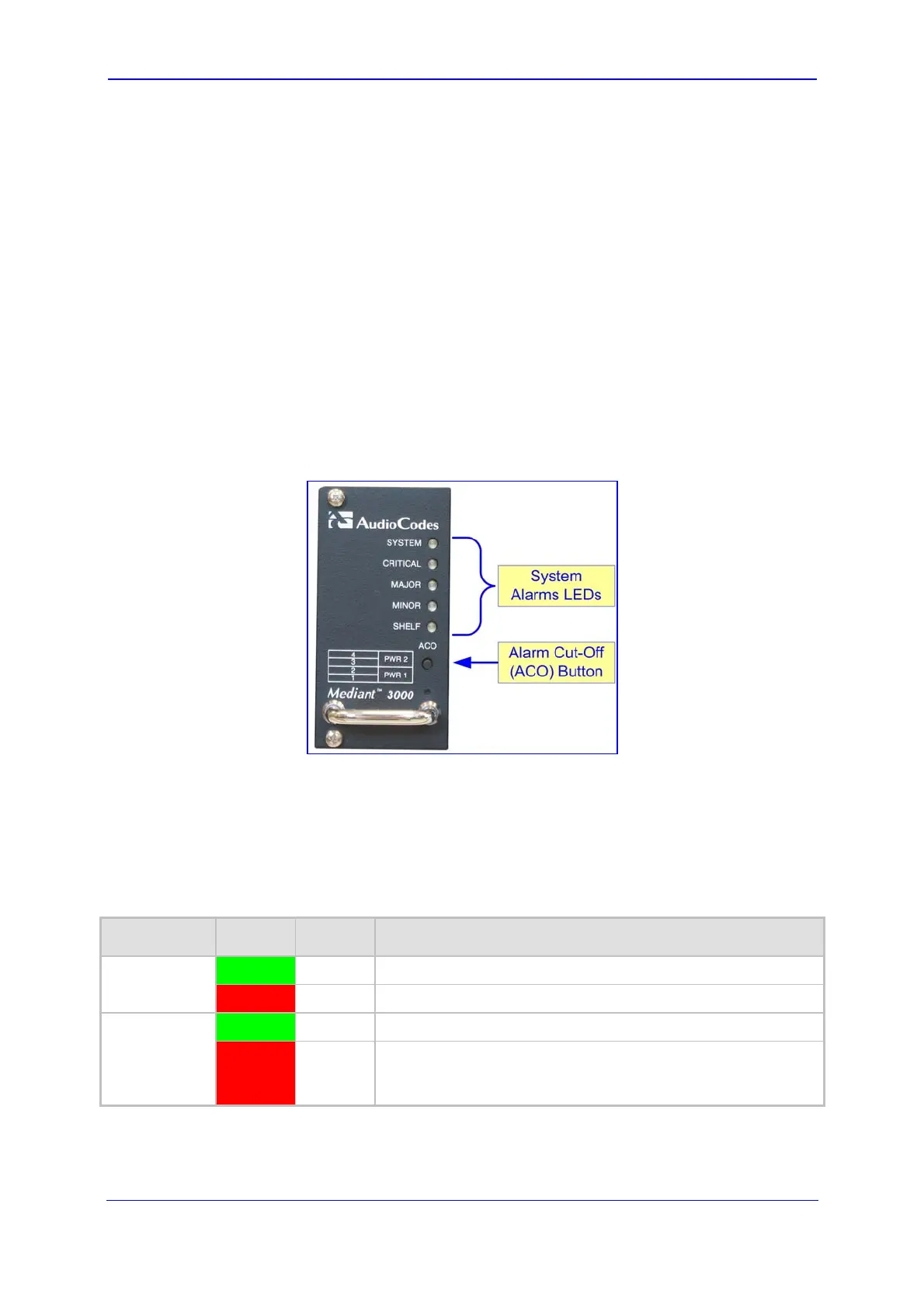
2.4 Alarm LEDs and ACO Button
The front panel of the Fan Tray module provides fault detection severity alarm LEDs and an
Alarm Cut-Off (ACO) button, as shown in the figure below:
Figure 2-7: Fan Tray Unit with Alarm LEDs and ACO Button
The ACO button is used to mute the external Telco alarm relay devices attached to the
Power Entry Module (refer to ''Power Supply'' on page 36). Whe
n the ACO button is
activated (by being pressed), all alarm relays are returned to normal position, de-activating
the alarm relay devices. The chassis LEDs and other device alarm signals are not affected.
The fault detection alarm LEDs (described in the table below) are connected to the Alarm,
Status and Synchronization blade.
Table 2-6: Fan Tray Module's Front-Panel Alarm LEDs Description
LED Color Status Description
SYSTEM Green
On Normal operation.
Red
On System failure.
CRITICAL Green
On No Critical alarms.
Red
On (Default when the device is powered on.) Detection of a
fault(s) categorized as “Critical” (i.e., Critical alarm). When this
LED is on, the MAJOR and MINOR LEDs are also lit.
 Loading...