Version 5.8 55 July 2009
Installation Manual 3. Installation
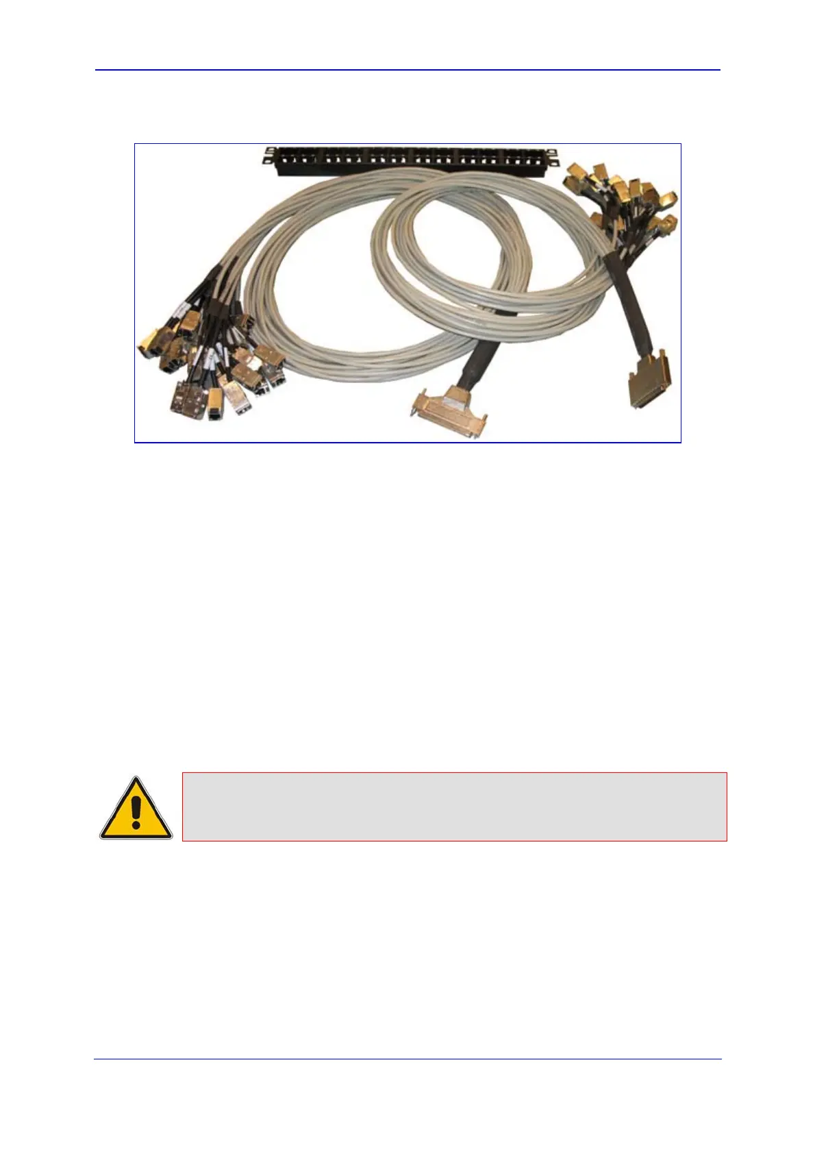
Figure 3-8: Patch Cable for 42 Spans
¾ To connect the E1/T1 trunk interfaces:
1. Prepare a SCSI cable of suitable length to connect between RTM-8410 housed in Slot
1 and the PBX/PSTN switch. The connector at the RTM-8410 end of the cable should
be wired as shown in the tables below (one cable for the 100-pin connector and a
second cable for the 68-pin connector).
2. For 42 and 84 spans configuration:
a. Attach the Trunk cable with a 100-pin male SCSI connector to the 100-pin female
SCSI connector labeled T1/E1 Trunks 1 to 25.
b. Attach the Trunk cable with a 68-pin male SCSI connector to the 68-pin female
SCSI connector labeled T1/E1 Trunks 26 to 42.
c. For trunks 43 to 84, repeat steps a and b, but for the RTM-8410 housed in Slot 4.
3. For 16-spans configuration: attach the Trunk cable with a 100-pin male SCSI
connector to the 100-pin female SCSI connector labeled T1/E1 Trunks 1 to 16.
4. Connect the other end of the Trunk cables to the PBX/PSTN switch.
Note:
For RTM-8410 in Slot 4, ignore the trunk numbers printed on the two SCSI
connectors.
 Loading...