B. Pin configurations
B.1 About General Purpose Inputs & Outputs (GPIO)
General Purpose inputs
Eight (8) opto-isolated general pur pose inputs are available. Thes e inputs are used to trigger the execution of macro files. For more
explanation about the association of a macro to a G PI, c onsult the user guide of the Com mu nicator touch panel.
Input voltage
The inputs can be directly driven from a TTL or CM OS output.
• The shape of the pulse must be rectangular.
• The duration of the pulse must be at least 1.6 milliseconds (shorter pulses are considered as a switch bounce)
• Minimum voltage : V
min
=3,3V
• Maximum voltage : V
max
=24V
External power supply
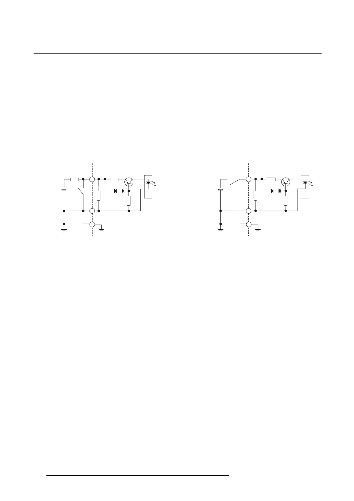
When interfacing with contact closure outputs, an ex ternal power supply needs to be p rovided. Depending upon the configuration a
suitable pull-up resistor needs to be added as well.
100R
GPIn P
GPIn N
Input to projector Internal projector
1k1
10k
+3.3V
to
+24V
Input to projector Internal projector
+3.3V
to
+24V
100R
GPIn P
GPIn N
1k1
10k
Image B-1
Cables
When long cable connec tions are required the us e of shielded c ables with twisted pairs is recomm ended. One twisted pair is to be
assigned to each GP Input pair.
How to make the connection
When the power s upply used to pro vide the DC voltage is isolated from ground (for exam ple in the case of a n A C adapter) it is
recommended that the minus pole of that pow er supply is connected to ground (or to the projector chassis). This will avoid high
common mode voltages at the projector GP Inputs. If that same power supply is used for other parts of the system, take care not to
create ground loops. In any c ase when shielded c ables are used that shield s hould be connected to the projector chas sis.
General Purpose outputs
Eight (8) opto-isolated outputs are available,
where f our are dedicated for TI. The other general pur pose outputs can be controlled
via software.
About a n output
The output c an gener ate a falling edge, rising edge, toggle or c ontinuous toggle.
• Generate Falling Edge – generate a falling edge on the external G PO port if the present state of the output is high. If the
present state of the external G P O is low, no edge will be generated.
• Generate Rising Edge – gen erate a rising edge on the external GP O port if the present s tate of the output is low. If the p resent
state of the external GPO is high, no edge will be gene rated.
• Generate Toggle – generate a toggle on the external GPO port. If the present state of the ou tput is low, a rising edge will be
generated, followed by a falling edge. If the present state of the output is high, a falling e dge w ill be gener ated, followed b y a
rising edge. The r ate of toggle w ill be the vertical sync rate (edge transition at each vsync). Pulse width = 20 milliseconds.
• Generate Continuous Toggle - This comm and w ill generate a continuous toggle of the external G P O por t. This toggle will
continue u ntil a Generate F alling Edge, Generate Rising Edge,orGenerate Toggle command is receiv ed. The rate of toggle is
24Hz. .
Output transistor
• Maximum output driving voltage : V
max
=70V
• Maximum current : I
max
=30mA
• Maximum power dissipation : 120 mW
138
R5977692 DP2K-S SERIES 10/12/2012
 Loading...


