10. Scheimpflug
10.3 Fixation of the Lens Holder front plate
When fixing the Lens Holder front plate
After performing the pr ocedure for Scheim pflug adjustment or Back Focal L ength adjustment the Lens Holder front plate mus t be
secured in such a way that it doesn’t disturb the result of the adjustment.
Necessary tools
• 10mm nut driver.
• 3mm Allen wre nch.
• 13mm nut driver.
How to fix the Lens Holder front plate?
Start t he fixation as follows (steps mu st be followed strictly) :
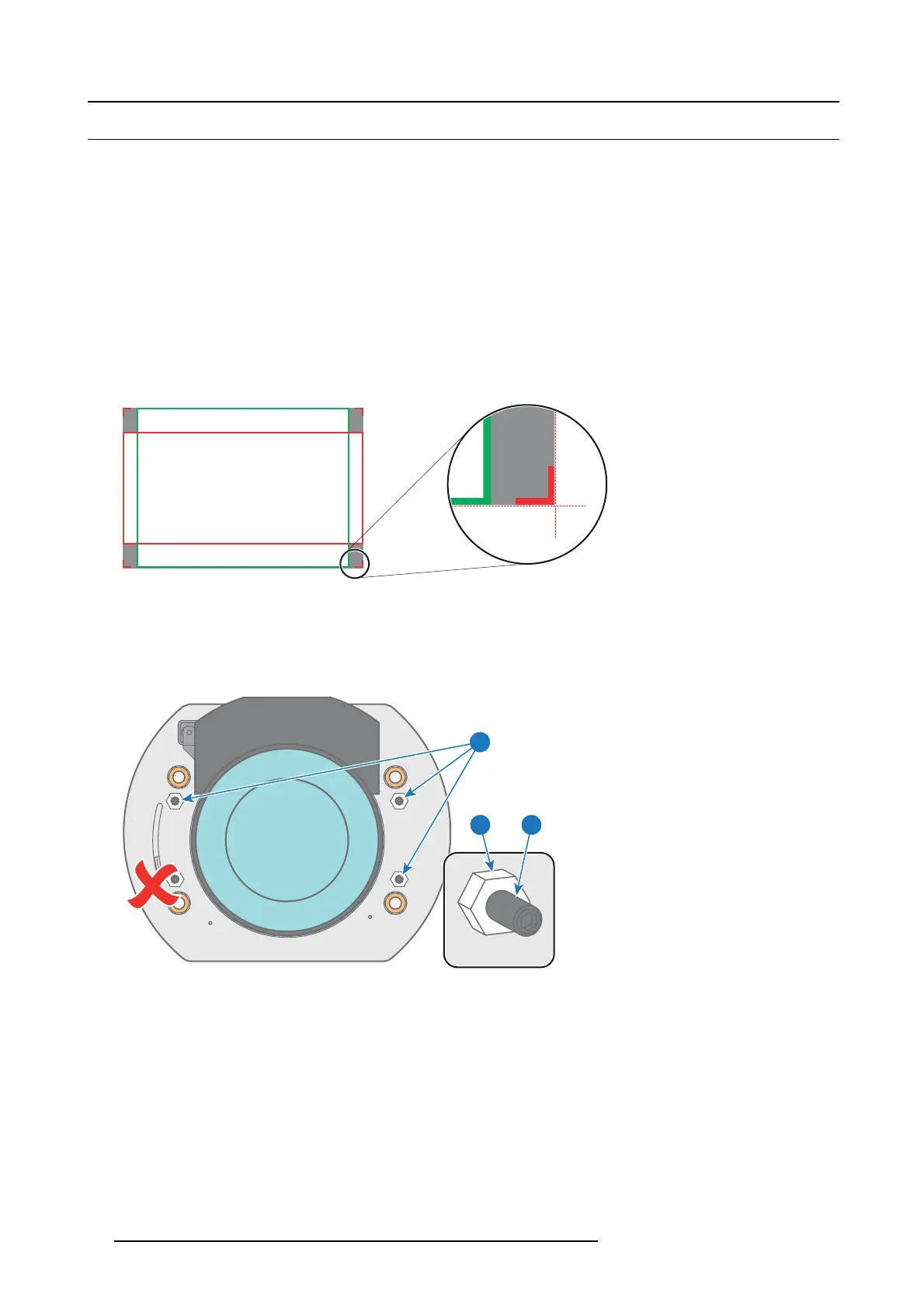
1. Project t he framing test pattern for F LAT & S CO PE .
2. Zoom the p rojected im age until the edges of the projected test pattern matches with the edges of the projection sc
reen.
FLAT
SCOPE
Image 10-10
3. Turn in the three set screws indicated with reference 11 image 1 0-11 without dis turbing the projected image. Tighten lightly . Do
not turn in the s et screw at the lower left of the Lens Holder !
Note: Ensure that the edges of the projected test pattern remain in place on the screen. Any movem ent of the image will affect
the Scheim p flug adjus tment.
4. Fas ten the lock nut (reference 21 im age 10-11) of the three set screws. Use a 10mm nut drive r. Ensure the image doesn’t m ove.
11
1121
Image 10-11
5. Gently turn (by hand ) the Scheimpflug adjustment nut at the lower left of the Lens Holder ( reference 4 image 10-12) against the
Lens Holder front plate without disturbing the projected image.
6. Turn in the set screw at the lower left
of the Lens Holder (reference 14 image 10 -12) without disturbing the projected image. Use
a 3mm Allen wrench.
Note: Ensure that the edges of the projected test pattern remain in place on the screen. Any movem ent of the image will affect
the Scheim p flug adjus tment.
Tip: Fasten the set s crew and the S cheim pfl ug nut alternately, without disturbing the projected image, until the Scheimpflug
nut and s et screw are completely tightened.
62
R5977692 DP2K-S SERIES 10/12/2012
 Loading...


