10. Scheimpflug
10.2 Scheimpflug adjustment
Necessary tools
• 3mm Allen wre nch.
• 13mm nut driver.
• 10mm nut driver.
Preparation steps:
1. Ensur e that the throw ratio of the installed lens matches the requirements of the application (projection distance a nd screen size).
2. Ensur e that the correct lens par ameters are activated. (See user guide of the Comm unicator ch apter Installation > Advanced >
Lens parameters)
Note: Selecting the wrong lens parameters will result in an unexpected behavior of the lens when using macros for switching
between FLAT and SCO PE (c hange in picture size and focus).
3. Perform a lens HOME & RETURN operation. (See user guide of the Communicator chapter Installation > Advan ced > Lens
parameters)
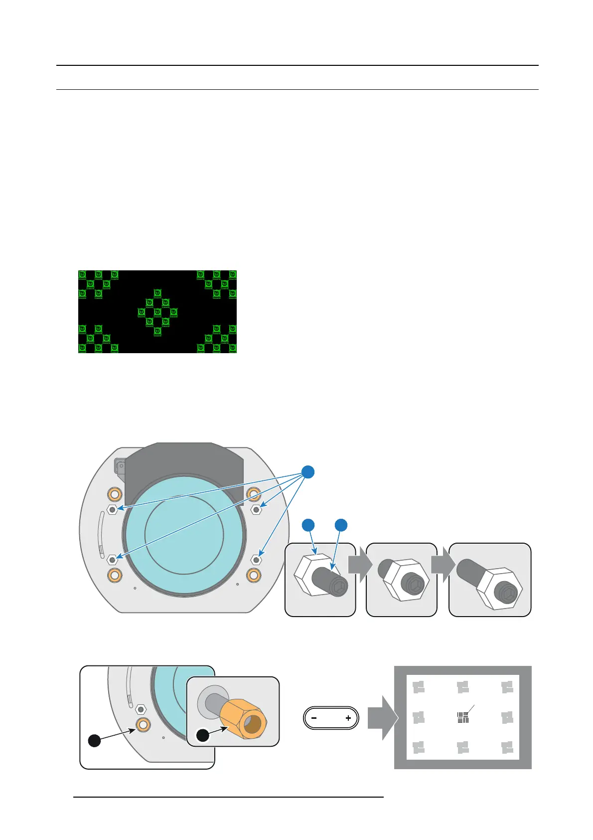
4. Project the gr een focus test pattern.
Image 10-3
5. Zoom the lens for maximum image on the screen (WIDE).
6. Is it possible to focus the c enter of the projected image?
If yes, the Back F ocal Leng th is O K. Proceed with the next step.
If no, th e B ack Focal Length needs realignment. Proceed with the procedure "Back Focal Length adjustment", page 64.
7. U nlock and turn out the 4 set screws (reference 11 im age 10-4) of the Len s Holder by 1 centimeter. U se a 10mm nut d river for
the lock nuts (reference 21 image 10-4) and use a 3mm Allen wrench for the set screws.
11
1121
Image 10-4
8. Fully loosen the Scheimpflug nut at the lower left of the Lens Holder (reference 4 image 10-5). Use a 13mm nut driver.
9. Optimize the focus of the projected im age in the c enter of the screen (F) using the motorized focus c ontrol (Local K eypad).
4
F
FOCUS
4
Image 10-5
60 R5977692 DP2K-S SERIES 10/12/2012
 Loading...


