10. Scheimpflug
10.1 Scheimpflug introdu ction
What is Scheimpflug?
The lens holder has to be adjus ted so that the “sharp focus plane” of the projected image falls together with the plane o f the screen
(Fp1→Fp2). This is achieve d by changing the distance between the DMD plane and the lens plane (Lp1→Lp2). T he c loser the lens
plane com es to the DMD plane the further the sharp focus plane will be. It can occur that you won’t be able to get a complete focused
image on the screen due to a tilt (or swing) of the lens plane with respect to the DMD plane. This is als o kn own as S heimpflug’s law.
To solve this the lens plane mus t be placed parallel w ith the DMD plane. This can be achieved by turning the lens holder to remove
the tilt (or swing) between lens plane and DMD plane (Lp3→Lp4).
SCREEN
DMD
Lp1
Lp2
Fp1
Fp2
SCREEN
DMD
Lp3
Lp4
Fp3
Fp4
(Scheimpflug)
Image 10-1
Scheimpflug principle
Scheimpflug principle
The "plane of sharp focus" c an be changed so that any plane ca n be brought into sharp focus. When the DM D plane
and lens plane are parallel, the plane of sharp focus will als o b e parallel to these two planes. If, however, the lens
plane is tilted with respect to the DMD plane, the plane of sharp focus will also be tilted according to geometrical and
optical properties. T he DMD plane, the principal lens plane and the sharp focus plane will intersect in a line be low the
projector for downward lens tilt.
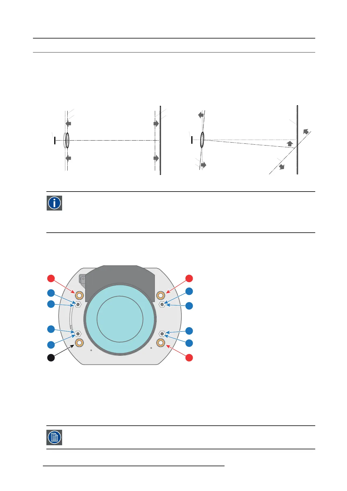
Scheimpflug adjustment points
The front plate of the Lens holder is equipped with four bronze (Sche impflug) nuts and four set screws with lock nut. T hese screws
and nuts are used for Scheimpflug adjustment.
1
11
14
4
21
24
13
3
23
2
12
22
Image 10-2
1Scheimpflug adjustment nuts No1: Influences the sharp focus plane in the lower left corner of the projected image.
2Scheimpflug adjustment nuts No2: Influences the sharp focus plane in the lower right corner of the projected image.
3Scheimpflug adjustment nuts No3: Influences the sharp focus plane in the upper right corner of the projected image.
4Scheimpflug nut No 4: without adjustment functionality.
11 Set screw for nut No1.
12 Set screw for nut No2.
13 Set screw for nut No3.
14 Set screw for nut No4.
21 Lock nut.
22 Lock nut.
23 Lock nut.
24 Lock nut.
Reference 1, 2 and 3 are adjustment points. Reference 4 is a locking point and NOT use d during Scheimp flug
adjustment.
58 R5977692 DP2K-S SERIES 10/12/2012
 Loading...


