B. Pin configurations
B.2 Pin configurations of the communication ports
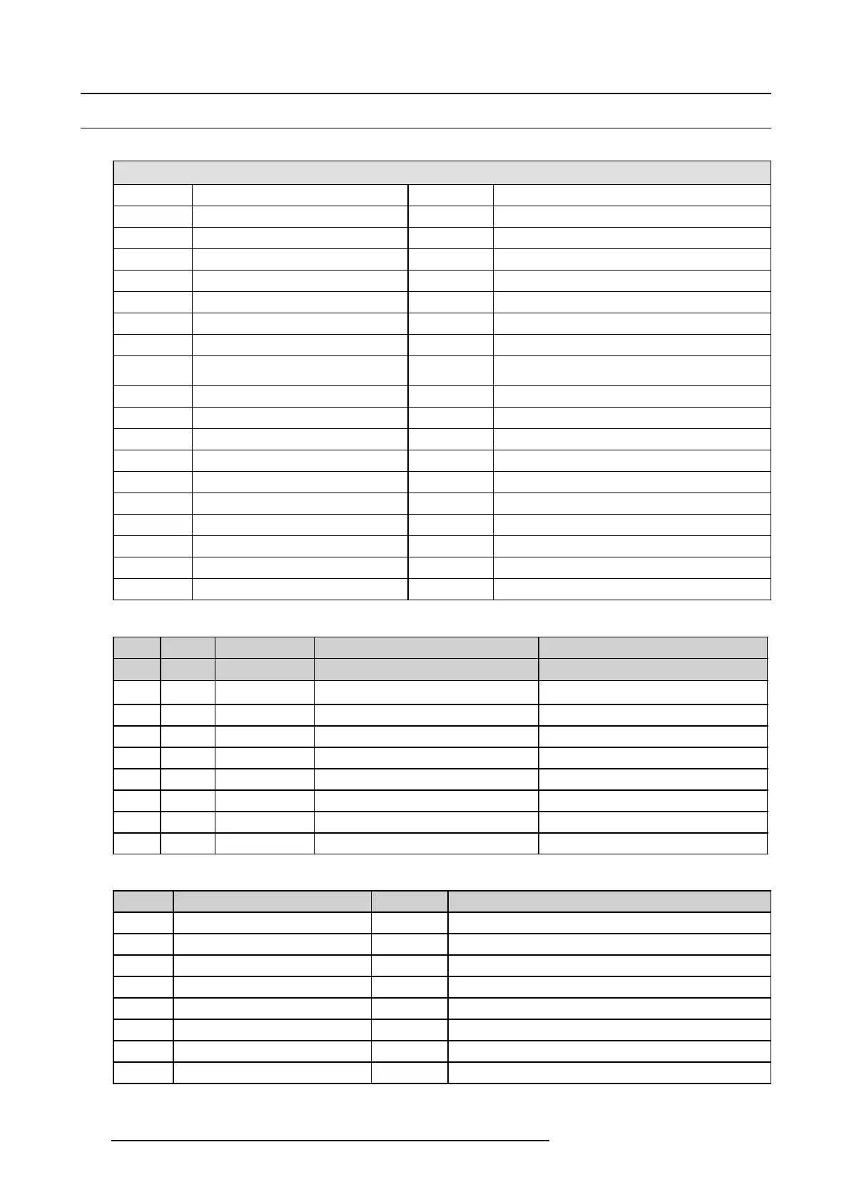
General purpose input/output (GPIO)
General Purpose In/Out
1
3D Input Reference P
20
3D Input Reference N
2
3D Display Reference P
21
3D Display Reference N
3
GPIN 3 P (reserved)
22
GPIN 3 N (reserved)
4
GPIN 4 P (reserved)
23
GPIN 4 N (reserved)
5
GPIN 5 P
24
GPIN 5 N
6
GPIN 6 P
25
GPIN 6 N
7
GPIN 7 P
26
GPIN 7 N
8
GPIN 8 P
27
GPIN 8 N
9
3D Output Reference P
28
3D Output Reference N
10 GPOUT 2 P (reserved) 29 G POU T 2 N (reserved)
11 GPO U T 3 P (reserved ) 30 GP OUT 3 N (reserved)
12 GPOUT 4 P 31 GPOUT 4 N
13 GPOUT 5 P 32 GPOUT 5 N
14 GPOUT 6 P 33 GPOUT 6 N
15 GPOUT 7 P 34 GPOUT 7 N
16 GPOUT 8 P 35 GPOUT 8 N
17 rese rve d 36 reserve d
18 rese rve d 37 reserve d
19 res e rve d
Ethernet port
10/100 Base-T – RJ4 5 port
1000 Base-T – RJ45 port
Pin Pair
Color
Description Description
13
white/green
TXD+ TX0+
23
green
TXD- TX0-
32
white/orange
RXD+ RX0+
4 1 blue
–
TX1+
5
1
white/blue
–
TX1-
62
orange
RXD- RX0-
7
4
white/brown
–
Rx1+
8 4 brown
–
RX1-
3D interface
Pin Name Pin Name
1 +12V 9 +12V
2 Grnd 10 3D Input Reference -
3 Grnd 11 3D Display Reference +
4 RS232 RX 12 3D Display Reference -
5
RS232 TX 13 CONN_3D MO DE -
6 CONN_3D_MODE + 14 CONN_SYNC -
7
CONN_SYNC + 15
-
8 3D Input Re ference +
140 R5977692 DP2K-S SERIES 10/12/2012
 Loading...


