Page 27
724-746-5500 | blackbox.com
Chapter 2: Overview
2.5 Device Views
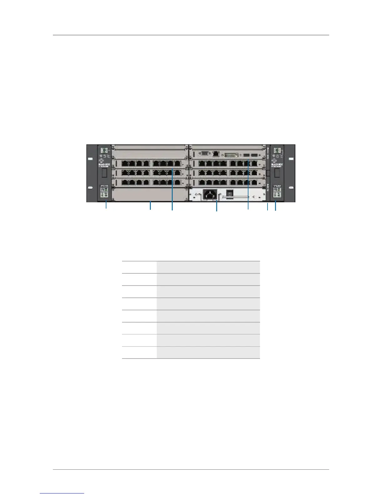
In Sections 2.5.1 through 2.5.4, Figures 2-2 through 2-5 illustrate the ServSwitch
DKM FX chassis models. Tables 2-4 through 2-7 describe their components.
NOTE: The following images of the chassis are fully populated with I/O cards and
are intended to be example diagrams. The chassis do not come with any
I/O cards. You need to purchase the I/O cards separately.
2.5.1 ServSwitch DKM FX 48-Port (ACX048)
1 2 3 4 5 6 7
Figure 2-2. Front view, ACX048.
Table 2-4. ACX048 components.
Number Component
1 Slot for fan tray
2 Slot for Power Supply Unit 1
3 Slot for I/O Boards 1–6
4 Slot for Power Supply Unit 2
5 Slot for CPU board
6 Slot for air filter
7 Slot for Fan Tray 2
 Loading...