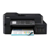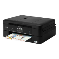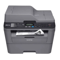

Do you have a question about the Brother MFC Series and is the answer not in the manual?
Lists general specifications for all models, including print head, droplet size, scanning method, CPU speed, and backup clock.
Details media sizes, weights, and types supported by various models for standard tray, photo tray, and ADF.
Specifies paper input capacity for standard tray and ADF, as well as output paper capacity.
Describes the LCD type and size, and touch panel availability across different models.
Details the memory capacity and backup method for all models.
Lists host interfaces, LAN, Wireless LAN, PictBridge, and USB memory support for various models.
Provides operating environment conditions, power consumption, machine dimensions, and weight for different models and regions.
Details paper types and sizes supported for Fax, Copy, and Printer operations.
Illustrates unprintable areas on cut-sheet paper and envelopes for various print features.
Specifies FAX capabilities including modem speed, transmission speed, and ITU-T group.
Lists printer specifications such as print speed, resolution, and auto duplex print.
Details copy speeds (ESAT, sESAT, FCOT) and resolution for different models.
Provides scan speed and resolution details for optical and interpolated scanning methods.
Lists driver support for operating systems like Windows and Macintosh.
Details network capabilities including Internet FAX, Wired LAN, and Wireless LAN security and setup.
Lists ink cartridge yields, ink bottle yields, and storage conditions for consumables.
Provides monthly volume, machine life, MTBF, and MTTR specifications.
Describes troubleshooting procedures for service personnel and covers typical cases and recovery procedures.
Lists essential precautions to prevent secondary troubles during troubleshooting and disassembly/assembly.
Provides cross-section drawings and details of document scanning and printer parts.
Explains the machine's self-diagnostic functions and displays error messages on the LCD.
Lists and describes various error codes, their causes, and references for solutions.
Details error messages displayed on the first line of the LCD, their status, and corresponding error codes.
Lists communication error codes, their causes, and references for troubleshooting.
Provides detailed troubleshooting steps for various problem categories.
Troubleshooting guide for specific error codes, including user checks and step-by-step solutions.
Addresses issues related to paper feeding, including feeding errors, jams, and wrinkling.
Details defective image issues and provides troubleshooting steps for various print quality problems.
Covers issues related to printing from a PC, driver settings, and network connectivity.
Troubleshooting steps for network printing issues, including connection failures.
Addresses issues with the LCD display, LEDs, control panel operation, and touch panel functionality.
Troubleshooting for document feeding issues such as inability to feed, double feeding, jams, and wrinkles.
Details defective scanned images like light, dark, distorted, or blank images, and provides solutions.
Troubleshooting for fax sending, receiving, and communication errors.
Covers miscellaneous issues like power problems, memory errors, security locks, and ink cartridge issues.
Essential warnings and precautions for safe and effective disassembly/assembly procedures.
Illustrates the packing method for ink cartridge and ink tank models.
Provides a visual catalog of screws used in the machine, including their types and sizes.
Lists screws with their location, type, quantity, and specified tightening torque.
Details lubricant types, lubrication points, and application amounts for maintenance.
Provides an overview of gears, including identification and numbering for the ADF drive gear.
Illustrates the correct routing paths for various harnesses, cables, and ink supply tubes.
Presents a flowchart of the disassembly process, including estimated times for each step.
Provides detailed step-by-step instructions for disassembling various machine components.
Covers preparations for disassembly, including transferring FAX data and disconnecting cables.
Instructions for opening and removing the jam clear cover.
Detailed steps for removing the head joint rubber, CR timing belt, and head/carriage unit.
Procedure for removing the document scanner unit, ADF unit, and document cover assembly.
Instructions for removing the CIS unit and its flat cable, including handling double-sided tape.
Details on removing ADF components like the document sponge and ADF top covers.
Steps for removing the control panel assembly and its related components.
Procedure for removing the upper cover and ink cartridge cover.
Instructions for removing the document scanner sensor assembly.
Procedure for removing the Wireless LAN PCB ASSY.
Detailed steps for removing and replacing the Main PCB ASSY, including harness disconnection.
Instructions for removing the MJ PCB ASSY and its related frames.
Procedure for removing the power supply unit, PCB, and related components.
Steps for removing the Carriage PCB ASSY, including flat cables and spacers.
Procedure for removing the ink refill ASSY, including ink extraction and tube removal.
Instructions for removing the ink absorber box and felt, with notes on ink handling.
Procedure for removing the CR encoder strip and encoder strip guard film.
Steps for removing the PF encoder disk and PF encoder sensor PCB ASSY.
Procedure for removing the carriage motor and its associated parts.
Instructions for removing the flushing base and flushing box.
Steps for removing the paper feed motor and associated components.
Procedure for removing the maintenance unit and its ink absorber felt.
Instructions for removing the paper feed roller and related parts.
Procedure for removing the platen assembly and its springs.
Steps for removing the paper ejection roller assembly and its components.
Procedure for removing the registration sensor PCB ASSY.
Instructions for removing the ink cartridge cover sensor assembly.
Steps for removing the paper pull-in roller and its components.
Procedure for removing and replacing the base pad on the paper tray.
Steps for adjustments after replacing the Main PCB, including firmware, CIS type, and serial number settings.
Procedures for adjustments after replacing the Head/Carriage unit, covering data updates and calibration.
Adjustments required after replacing the document scanner or CIS unit, including CIS type and scanning checks.
Steps for adjusting the touch panel and checking LCD and control panel operations.
Procedure for resetting purge and flushing counts after replacing the ink absorber or flushing box.
Adjustments needed after replacing paper feeding parts or the maintenance unit.
Details on entering and operating the maintenance mode for checks, settings, and adjustments.
Instructions on how to access the maintenance mode for service personnel and end users.
Explains the key operations within the maintenance mode based on model panel specifications.
A comprehensive list of maintenance mode functions, their descriptions, and reference sections.
In-depth explanations and operating procedures for various maintenance mode functions.
Initializes EEPROM parameters, user switches, and worker switches to default values.
Scans print patterns to create and write head calibration data into flash ROM for high-precision printing.
Prints light and dark level data for scanning compensation, useful for optimizing scan quality.
Tests ADF performance by counting document feeds and displaying the count on the LCD.
Prints a test pattern to check print quality and serial number for service personnel.
Allows customization of machine functions via worker switches and printing their settings.
Checks the normal operation of the LCD display on the control panel across different model types.
Verifies the normal operation of control panel keys by checking corresponding LCD numbers.
Transfers EEPROM settings to another machine as fax data for backup or transfer.
Checks the normal operation of various sensors and their status displays on the LCD.
Outputs a list of telephone numbers dialed for FAX models.
Customizes machine settings for language and destination countries based on EEPROM codes.
Transfers received FAX data, activity reports, communication lists, and logs as fax data.
Adjusts the scanning start and end positions of the ADF for optimal scan accuracy.
Obtains white/black level data for the CIS scanner and saves it with correction values to EEPROM.
Checks cartridge information like color, destination, size, and data version in the IC chip.
Optimizes paper feed roller and ejection roller rotations using correction values for paper feeding accuracy.
Checks CIS unit movement and allows specifying CIS type in EEPROM parameters.
Moves the Head/carriage unit to an adjusted position for calibration and alignment procedures.
Aligns vertical lines printed by the Head/carriage unit and corrects inclination/corrugation.
Adjusts the left, right, and bottom margins for borderless printing.
Optimizes drive conditions of Head/carriage units based on their property data for print quality.
Checks if the traveling speed of the Head/carriage unit is within the specified range.
Customizes machine settings like language, functions, and worker switches for specific regions.
Moves the Head/carriage unit to the center to facilitate removal of paper particles and dust.
Performs various purge operations (normal, periodical, power, initial, user, engine setup) for ink system maintenance.
Prints the machine's log information, including error history and operational data.
Adjusts the detection area of the touch panel for accurate input response.
Displays various log information items on the LCD, such as serial number, firmware version, and error history.
Displays the error code of the last error that occurred on the machine.
Outputs the FAX transmission log to the telephone line for remote analysis of FAX problems.
Provides workarounds for untypical environments by changing machine settings via assurance mode switches.
Provides access to other service functions like firmware version display and log retrieval.
Instructions on how to check the firmware version on different panel models.
Moves the Head/carriage unit to the center of its travel for easier access and cleaning.
Retrieves log information from the machine to a connected PC as electronic data.
Circuit diagram for the MJ PCB, showing component layout for different regions.
Circuit diagram for the power supply PCB designed for 100 V systems.
Circuit diagram for the power supply PCB designed for 200 V systems.
Provides a comprehensive overview of the machine's wiring connections between various components.
States that there are no parts that require periodic replacement.
Shows the location and coding information for the machine's serial number label.
Details the location and coding information for the head property label on the Head/carriage unit.
Instructions on how to delete all user setting information stored in the EEPROM.
Procedure for installing the maintenance driver for Windows 2000 and XP systems.
Installation procedure for the maintenance driver on Windows Vista, 7, and 8 operating systems.
General safety guidelines for using the machine safely, including electrical and fire hazard warnings.
Specific safety instructions related to the proper handling and use of the power cord.
Warnings regarding fire risks associated with improper use of the machine or cleaning agents.
Important cautions to prevent minor injuries or damage during machine operation.
General precautions to prevent secondary troubles during troubleshooting and disassembly/assembly.
FCC compliance statement for Class B digital devices, including interference guidelines.
Wireless connection compliance statement for Mexico.
Industry Canada compliance statement for devices with telecommunications and/or radio interfaces.
Notice regarding applicable Industry Canada technical specifications for MFC models.
Guidance on using machines within the USA and Canada, and warnings about overseas use.
Important note regarding connecting to LAN connections susceptible to over-voltages.
Declaration of conformity with essential requirements for European Community directives.
Declaration of conformity with R&TTE Directive provisions for models with telecommunications interfaces.
Indicates that the product supports Wireless LAN functionality.
Compliance with EN55022/Class B and USB cable length recommendations.
Information on proper disposal of the product/battery at the end of its life according to WEEE directives.
