1 Basic Principles of PLC Ladder Diagram
DVP-PLC Application Manual
1-8
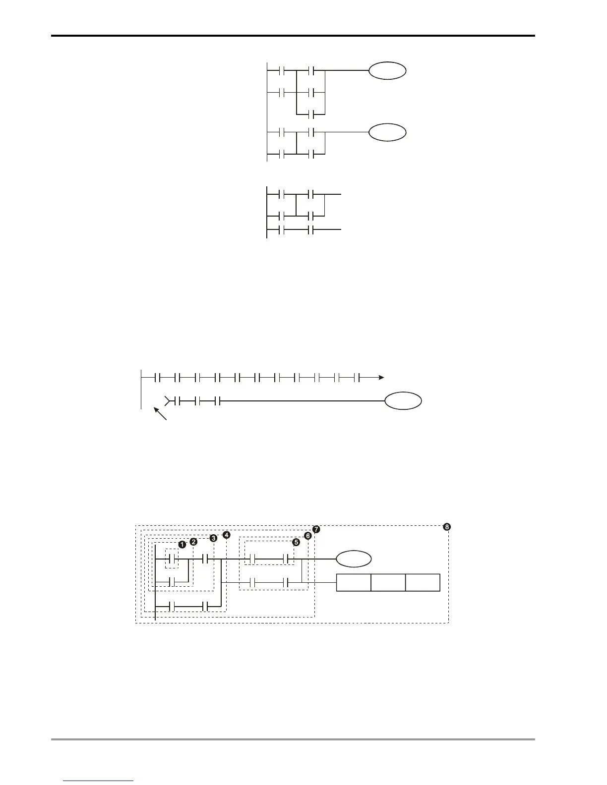
An independent network
Network 1
Network 2
An incomplete network
1.4 How to Edit a PLC Ladder Diagram
The editing of the program should start from the left power line and ends at the right power line, a row after
another. The drawing of the right power line will be omitted if edited from WPLSoft. A row can have maximum 11
contacts on it. If 11 is not enough, you can continuously connect more devices and the continuous number will be
generated automatically. The same input points can be used repeatedly. See the figure below:
X0 X1 X2 X3 X4 X5
Y0
X11 X12 X13
X6 X7 X10 C0 C1
00000
00000
Continuous number
The operation of the ladder diagram program is scanning from top left to bottom right. The coil and the operation
frame of the application instruction belong to the output side in the program and are placed in the right if the ladder
diagram. Take the figure below for example, we will step by step explain the process of a ladder diagram. The
numbers in the black circles indicate the order.
X0 X1 Y1 X4
M0
X3
M1
T0
M3
Y1
TMR T0 K10
The order of the instructions:
1 LD X0
2 OR M0
3 AND X1
4 LD X3
AND M1

 Loading...


