8 Application Instructions API 100-149
DVP-PLC Application Manual
8-17
API Mnemonic Operands Function
107
LRC P
Checksum LRC Mode
Controllers
ES/EX/SS SA/SX/SC EH/SV
Bit Devices Word Devices Program Steps Type
OP
X Y M S K H KnX KnY KnM KnS T C D E F
S
*
n * * *
D *
LRC, LRCP: 7 steps
PULSE 16-bit 32-bit
ES EX SS SA SX SC EH SV ES EX SS SA SX SC EH SV ES EX SS SA SX SC EH SV
Operands:
S
: Start operation device for ASCII mode checksum n: Number of calculated bits D: Start device for storing the
operation result LRC checksum: See remarks.
Explanations:
1. Range of n: K1 ~ K256
2. See the specifications of each model for their range of use.
3. Flag: M1161 (switching between 8/16 bit modes)
4. n has to be even. If n does not fall within its range, an operation error will occur, the instruction will not be
executed, M1067, M1068 = On and D1067 will record the error code H’0E1A.
5. In 16-bit conversion mode: When M1161 = Off, S divides its hex data area into higher 8 bits and lower 8 bits
and performs LRC checksum operation on each bit. The data will be sent to the higher 8 bits and lower 8 bits in
D. n = the number of calculated bits.
6. In 8-bit conversion mode: When M1161 = On, S divides its hex data area into higher 8 bits (invalid data) and
lower 8 bits and performs LRC checksum operation on each bit. The data will be sent to the lower 8 bits in D
and occupy 2 registers. n = the number of calculated bits. (All higher bits in D are “0”.)
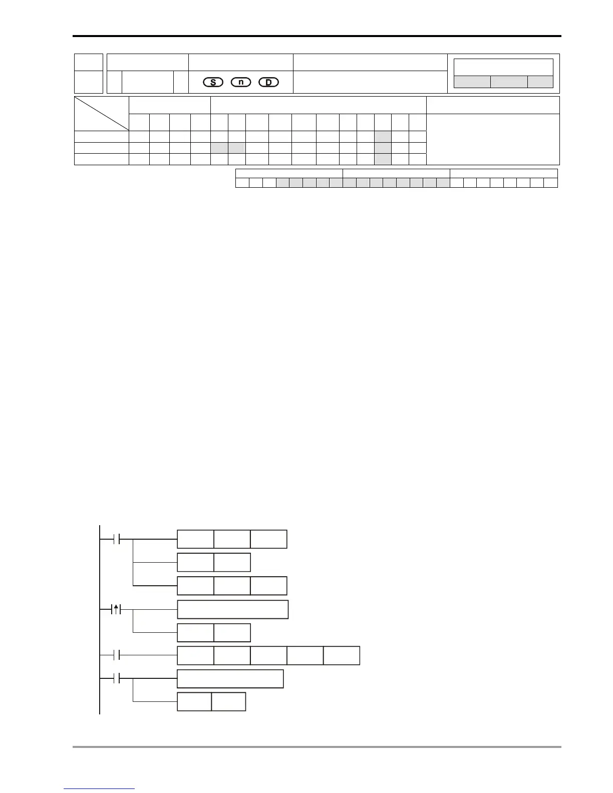
Program Example:
When PLC communicates with VFD-S series AC motor drives (In ASCII mode, M1143 = Off), (In 8-bit mode, M1161 =
On), the sent data write in advance the 6 data read starting from H2101 of VFD-S.
MOV D1120H86
M1002
SET M1120
SET M1122
MOV D1129K100
X10
M1123
RST
M1123
RS D100
K17
D120 K35
pulse
receiving completed
Process of receiving data
Set up communication protocol to 9600, 7, E, 1
Retain communication protocol
Set up communication time-out: 100ms
Set up transmission request
Sending/receiving of data is completed.
The flag is reset.
Write in sent data in advance
sending request pulse

 Loading...


