9 Application Instructions API 150-199
DVP-PLC Application Manual
9-30
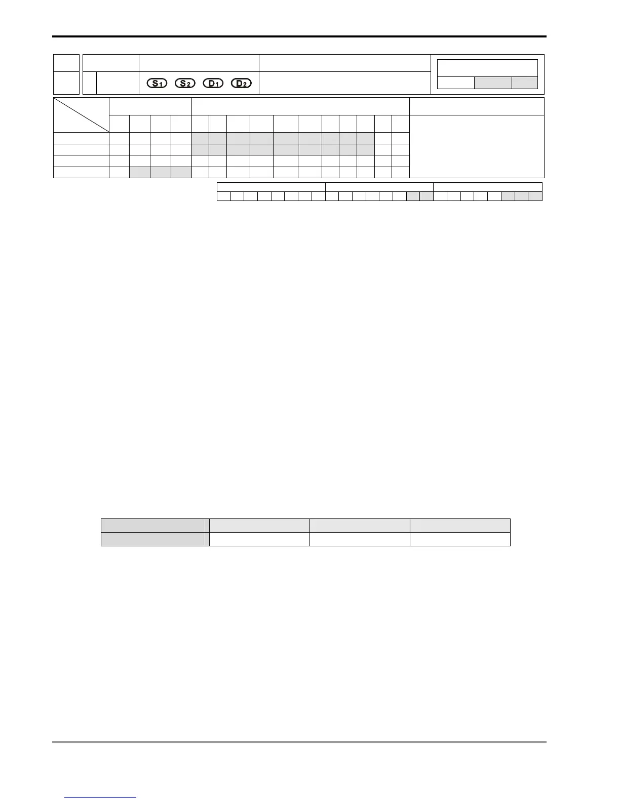
API Mnemonic Operands Function
159
D DRVA
Drive to Absolute
Controllers
ES/EX/SS SA/SX/SC EH/SV
Bit Devices Word Devices Program Steps Type
OP
X Y M S K H KnX KnY KnM KnS T C D E F
S
1
* * * * * * * * * * *
S
2
* * * * * * * * * * *
D
1
*
D
2
* * *
DRVA: 9 steps
DDRVA: 17 steps
PULSE 16-bit 32-bit
ES EX SS SA SX SC EH SV ES EX SS SA SX SC EH SV ES EX SS SA SX SC EH SV
Operands:
S
1
: Number of output pulses (absolute designation) S
2
: Pulse output frequency D
1
: Pulse output device
(please use transistor output module) D
2
: Output device for the signal of rotation direction
Explanations:
1. See remarks for the setting range of S
1
, S
2
, D
1
and D
2
.
2. S
1
and S
2
of SC series MPU only support device K, H and D.
3. Flag: see remarks of API 158 DRVI for more details.
4. S
1
is the number of output pulses (absolute designation). For EH/EH2/SV series MPU, the 16-bit instruction
can designate the range -32,768 ~ +32,767. The range designated by 32-bit instruction is -2,147,483,648 ~
+2,147,483,647. For SC series MPU, the 32-bit instruction can designate the range -2,147,483,648 ~
+2,147,483,647. “+/-” signs indicate forward/backward directions.
5. S
2
is the designated pulse output frequency. For EH/EH2/SV series MPU, the 16-bit instruction can designate
its range 10 ~ 32,767Hz. The range designated by 32-bit instruction is 10 ~ 200,000Hz. For SC series MPU,
the 32-bit instruction can designate the range 100 ~ 100,000Hz.
6. EH series MPU has two groups of A/B phase pulse output, CH0 (Y0, Y1) and CH1 (Y2, Y3). EH2/SV series
MPU has four groups of A/B phase pulse output, CH0 (Y0, Y1), CH1 (Y2, Y3), CH2 (Y4, Y5) and CH3 (Y6, Y7).
See remarks for the setup methods.
7. Pulse output device D
1
in different models
Model SC MPU EH MPU EH2/SV MPU
Pulse output end Y10, Y11 Y0, Y2 Y0, Y2, Y4, Y6
8. When S
1
is larger than the current relative position, D
2
will be Off; when S
1
is smaller than the current relative
position, D
2
will be On. D
2
will not be Off immediately after the pulse output is over; it will be Off only when the
drive contact of the instruction turns Off.
9. For EH/EH2/SV series MPU, S
1
is
- The 32-bit data stored in the present value registers D1337 (high word) and D1336 (low word) of CH0 (Y0,
Y1).
- The 32-bit data stored in the present value registers D1339 (high word) and D1338 (low word) of CH1 (Y2,
Y3).
- The 32-bit data stored in the present value registers D1376 (high word) and D1375 (low word) of CH2 (Y4,
Y5).
- The 32-bit data stored in the present value registers D1378 (high word) and D1377 (low word) of CH3 (Y5,

 Loading...


