4 Step Ladder Instructions
DVP-PLC Application Manual
4-1
4.1 Step Ladder Instructions [STL], [RET]
Mnemonic Function Program steps
STL
Step Transition Ladder Start 1
Controllers
ES EX SS SA SX SC EH SV
Operand
S0 ~ S1023
Explanations:
STL Sn constructs a step. When STL instruction appears in the program, the program will enter a step ladder diagram
status controlled by steps. The initial status has to start from S0 ~ S9. RET instruction indicates the end of a step
ladder diagram starting from S0 ~ S9 and the bus returns to a normal ladder diagram instruction. SFC uses the step
ladder diagram composed of STL/RET to complete the action of a circuit. The No. of S cannot be repeated.
Mnemonic Function Program steps
RET
Step Transition Ladder Return 1
Controllers
ES EX SS SA SX SC EH SV
Operand
N/A
Explanations:
RET indicates the end of a step. There has to be a RET instruction in the end of a series of steps. One PLC program
can be written in maximum 10 steps (S0 ~ S9) and every step should end with a RET.
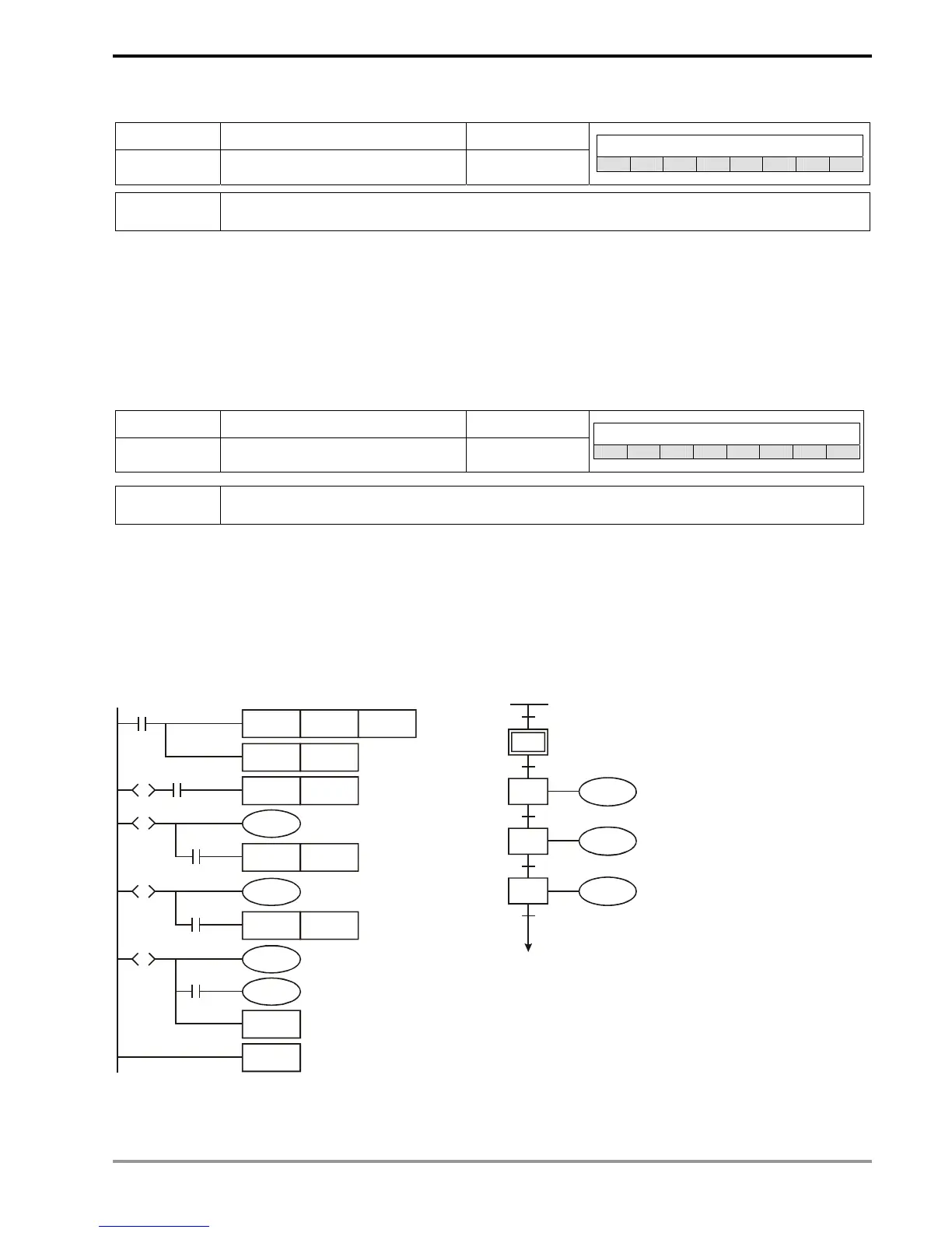
Program Example:
Ladder diagram: SFC:
M1002
ZRST S0 S127
SET S0
SET S20
Y0
SET S30
Y1
SET S40
Y2
S0
RET
END
X0S0
S
S20
S
X1
S30
S
X2
S40
S
X3
S0
S20
S30
S40
S0
M1002
X0
X1
X2
X3
Y0
Y1
Y2

 Loading...


